The adventures of Anika J

The friendliest place on the web for anyone who enjoys boating.
If you have answers, please help by responding to the unanswered posts.

Kit_L

Senior Member
Joined
Mar 12, 2016
Messages
476
Location
Australia
Vessel Name
Suu Kyi
Vessel Make
Custom 40' catamaran
I named this thread in honour of Wayfarer's "Adventures of Sylphide", simple because I have enjoyed that thread so much.

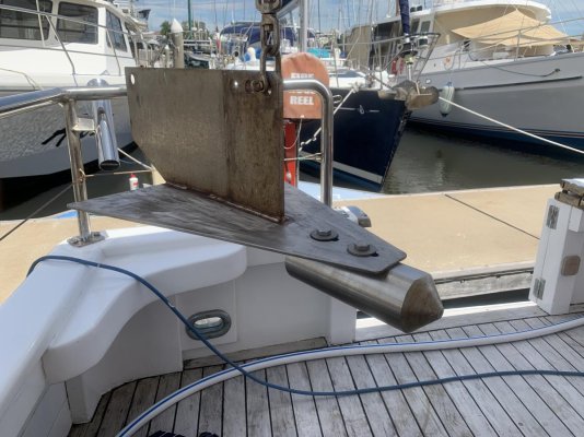
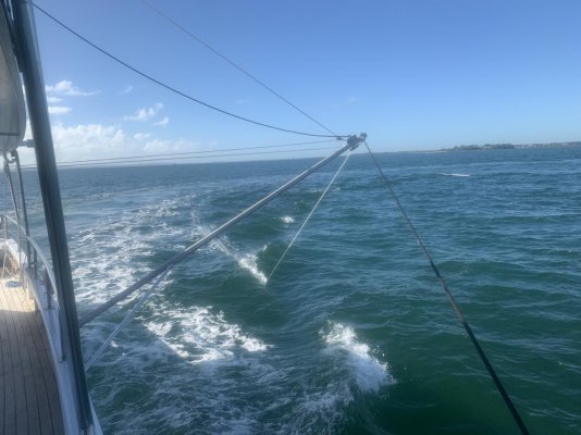
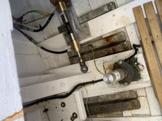
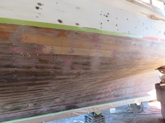
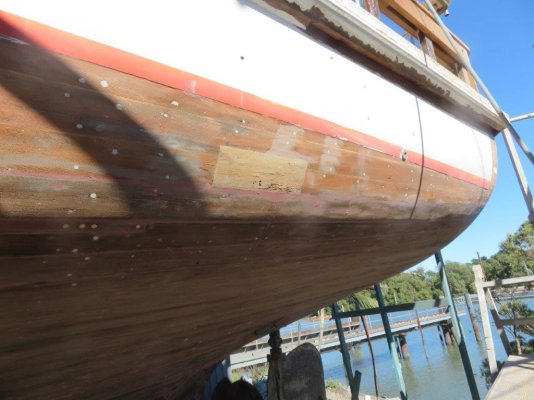
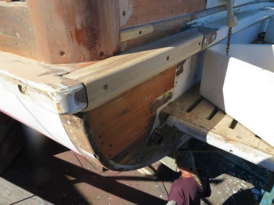
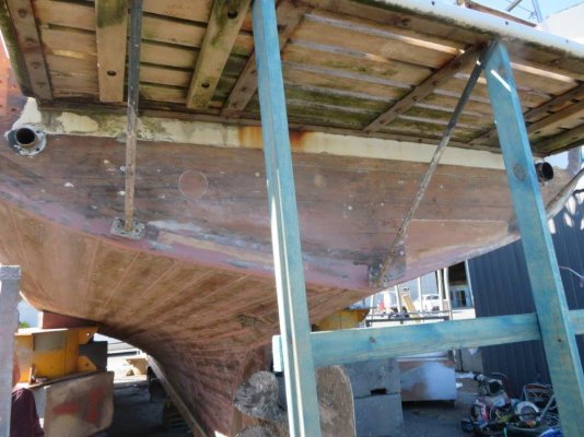
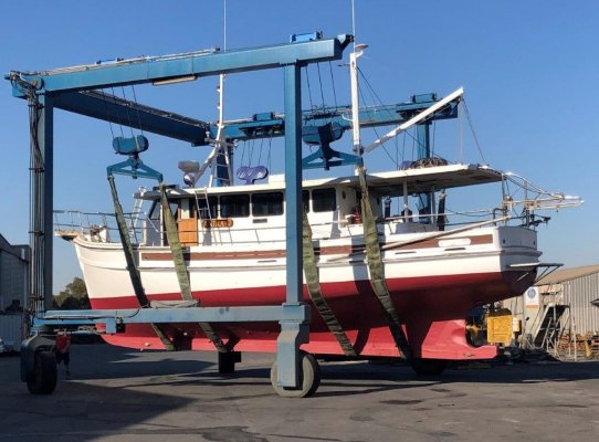
We (Olivia, the Admiral) and I bought Anika J a couple of weeks ago, and I am in Manly, Qld, working on a number of things that need to be done before we head offshore, primarily rigging and adapting the paravanes, changing the rudder geometry to improve slow speed manoeuvring, modifying the main cabin settee to become my bunk while underway, adding power points (I will be working from the vessel) and generally learning her systems. First an image:

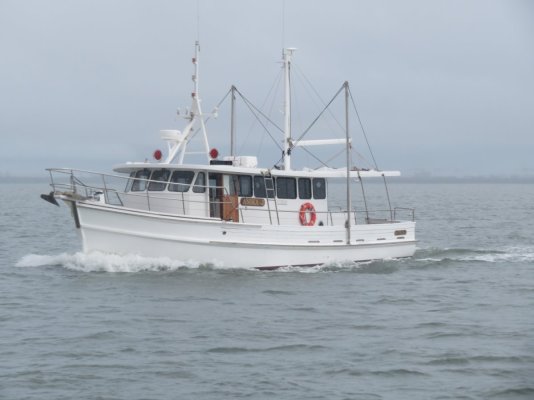
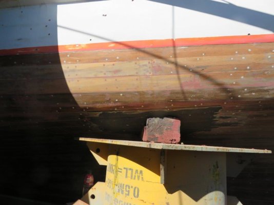
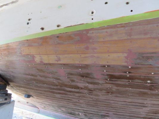
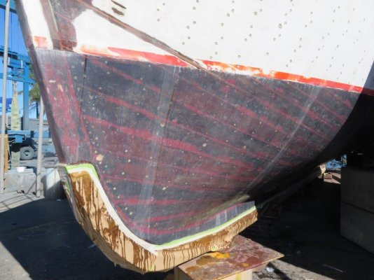
She is a Holmes-designed and built 48' timber boat, with a draft of 6'3" (1.9m), a beam of 4.2m (14'), and a displacement of approximately 30+ tons.

I will make these posts short, and if anyone can advise me how to post images and place text in between, I will be grateful. If this is not possible, I will post one or more images that are related to the text for ease of reading.
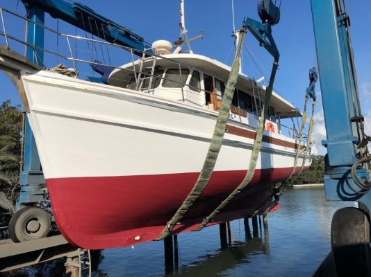
 

Attachments

  • 0_4.jpg
    0_4.jpg
    98.7 KB · Views: 149
Last edited:
Today's task was to improve low-speed handling. Anika J has a deep, long keel, with all the advantages that has—and the disadvantages, too. I modified the rudder on Seabiscuit, following the lead of the commercial fishermen in our area, by attaching a piece of stainless right angle bracket vertically on the rudder, perpendicular to the prop wash, like this:

I am now able to turn Seabiscuit in slightly over her length in still water, in three moves: hard over to port, short burst forward, and this gets the bow swinging; astern (rudder in same position); prop walk continues the bow swing (left-handed prop); this washes off any forward momentum; and repeat (one or two times more).

But our new boat, Anika J, is presently in the water, and I wanted to see if we could improve her rudder deflection angle in situ. We disassembled the rudder gear, and used a puller to remove the tiller arm:

The tiller arm has had the ram hole re-drilled, 36mm closer to the rudder post, and I moved the ram support block assembly forward by a similar amount to maintain the original geometry. I will show the arm refitted in the next post. Reassembling yesterday and testing showed that moving the arm attachment point by this amount improved the deflection angle by 10° or so. We are making a new bracket to hold the rudder arm limiting chains, so that nothing fouls with the additional movement.

The grey bars are lead ingots, for trim, we assume.
 

Attachments

  • 60273254516__28F3C3FB-EF1B-4653-A382-2FBF18D6EA5E 2.jpg
    60273254516__28F3C3FB-EF1B-4653-A382-2FBF18D6EA5E 2.jpg
    197.3 KB · Views: 118
  • IMG_4888.jpg
    IMG_4888.jpg
    102.2 KB · Views: 109
  • IMG_5024.jpg
    IMG_5024.jpg
    154.5 KB · Views: 110
Last edited:
Great looking vessel you have there, look forward to your improvements.
Cheers
 
Thank you, John,

The listing that caught my attention was this:

https://yachthub.com/list/boats-for-sale/used/power-boats/holmes-48-motor-cruiser/243116

I will attach some bare-hull images below; the hull was out of the water for 7 months, and about 10 planks were replaced, and much work done on the transom. Once the hull was completely dry and the repairs effected, the caulking was removed and epoxy putty replaced it. Then the hull was 'tri-axially glassed': this was a new technique to me, but common on commercial wooden vessels here: to wraps at 90° from upper hull to keel, and a final wrap across the hull.

The list of work done by the immediately previous owner is impressive: rot in the cabin rook repaired, full paint job, full engine service (including injectors), impellers and hoses replaced (and a full set of spares left in the ER); all fluids replaced, including gearbox, all filters replaced, new 24V deckwash installed, new morse control, anchor chain removed, pressure washed, and marked; exhaust boxes and hoses replaced, hydraulic steering serviced, Capstan dismantled and serviced, new hopper window fitted to rear bulkhead; full service to air conditioning, including one new pump, all fire extinguishers replaced, new restraining chains fitted to rudder (we will have to change these once I have fitted the modified tiller arm); E floor repainted; bulwarks painted; new upholstery in saloon and cabin; new carpet, underlay and soundproofing; new Epirb and flares; all skin fittings pulled when hull was glassed, too. There's more, but these are the main ones.
 

Attachments

  • IMG_0983.jpg
    IMG_0983.jpg
    69.3 KB · Views: 87
  • IMG_0984.jpg
    IMG_0984.jpg
    84.4 KB · Views: 87
  • IMG_0985.jpg
    IMG_0985.jpg
    109.2 KB · Views: 84
  • IMG_0986.jpg
    IMG_0986.jpg
    90.7 KB · Views: 92
  • IMG_0987.jpg
    IMG_0987.jpg
    100.7 KB · Views: 95
  • IMG_0988.jpg
    IMG_0988.jpg
    97.4 KB · Views: 83
  • IMG_0989.jpg
    IMG_0989.jpg
    103 KB · Views: 83
  • IMG_0990.jpg
    IMG_0990.jpg
    115.9 KB · Views: 81
  • IMG_2050.jpg
    IMG_2050.jpg
    120.7 KB · Views: 89
  • IMG_3072.jpg
    IMG_3072.jpg
    129 KB · Views: 86
Very interesting, keep them coming. It has some history. I know it is glassed now, but what timber was used in the hull?
You must have good boat design/maintenance skills, where do they come from?

"Holmes" is a well known boating name in Sydney. Builders, 18ft sailor ,and currently marine surveying.
 
The grey bars are sacrificial zincs. Make sure you keep them up but don't over zinc the boat. In the Cruising Down Under section in Thistle rudders you will see the rudder I have on Tidahapah. It has a fishtail on the trailing edge and over flow and underflow plates to direct the water stream. Reasonably efficient design.
 
The grey bars I was referring to are found in the images of the lazarette (third image, second post); they are stamped "Lead". The circular grey things on the Seabiscuit rudder (the one with the stainless angle pseudo fishtail modification) are anodes; sorry if I wasn't clear.

The images show the modified rudder arm reinstalled, with the new stainless rotating tab to hold the restraining chains. Refitting the chains is tomorrow's task.

The new hole for the hydraulic ram is 36mm closer to the shaft, as mentioned; I moved the ram support block just over 30mm forward, to preserve the original geometry. On reassembly, we found that the ram had been mounted wrongly before (it was sitting on top of the rudder arm). Mounting the ram Heim joint under the arm improves the geometry considerably. The whole rudder assembly was serviced back in October 2019, including the replacement of the lines for the hydraulic system, so we think that this is when the error was made.

Two of the images show full port and starboard rudder deflection, following the modifications. When the instrument tech. visits, I have asked him to bring a rudder angle indicator, to measure the actual deflection angles. From eye, they have increased 10° or so.

To the gurus here: how can I rotate images to the correct orientation in the post?
 

Attachments

  • IMG_4642.jpg
    IMG_4642.jpg
    171.6 KB · Views: 60
  • IMG_4635.jpg
    IMG_4635.jpg
    153.7 KB · Views: 67
  • 60343869698.jpg
    60343869698.jpg
    102.8 KB · Views: 55
  • IMG_4634.jpg
    IMG_4634.jpg
    175.7 KB · Views: 57
  • IMG_4633.jpg
    IMG_4633.jpg
    133.5 KB · Views: 57
  • IMG_4632.jpg
    IMG_4632.jpg
    152.6 KB · Views: 59
Last edited:
To BruceK: I have been on an extremely rapid learning curve since moving to the South Coast six years ago, and joining Marine Rescue . I have been working with two shipwrights there and a number of engineers, plus I have a background in science, and modified cars. I am a researcher and writer by profession. Here I have been working under the guidance of a boat designer and builder, and drawing on his network of experts. I have done all the work (apart from drilling the new hole in the tab; had to take it to the shop to get that done). I am literally learning many new things each day!

The next chapter will be the paravanes: the original ones I calculated at 310 square inches, and we felt we did not need such big ones. They have been cut down to 210 square inches approximately, and the bullets removed (they were huge and heavy) and about 30% of their length has been cut off. As well, a flat was machined on top for their full length, holes drilled and tapped, and a slot cut in the wing of each fish to make the bullet positions adjustable. Images to come.
 
She may require a bit of ballast re the lead. I know when Bertie (Bert Ellis) boat builder was working on her as a deck hand and general builder the fish were stowed at the stern either side of the Duck Board. From what Bert has told me ( they worked all up and down the coast and into Papua New Guinea) the stabilisers worked very well.
 
To the paravane gurus out there: assuming a fish is suspended from its intended hole, what downward angle are we looking for at rest? The way the fish have been re-designed, we can easily set any angle we want, on land.

Benn: yes, I am hoping to find many more of these bars as I dig into the engine room. Much of the ER sole is screwed down, so I have not been able to look yet. She feels like a ballasted boat but until I find these stacked down low, I won't know for sure.

Re. Bert Ellis: apparently in the big refit (some eight–ten years ago, but who really knows when this happened!), Bert used a chainsaw to cut the old house off... before building the current, beautiful one. I assume he's still working?

Re. the fish: as I bought the boat, these were really really heavy (about 25kg) and seemed like complete overkill. I measured/calculated each at 310 square inches. The Kolstrand site suggests that the 192 square inch models are the right ones for boats 30–50 feet; the 300 square inch ones are for boats 50–60 feet.

We are cutting ours down to 210 square inches and making the bullets adjustable (fore and aft) on the wings. And we are getting circular brackets made so the fish can be stored outboard of the capping rail near the booms (which themselves have been changed from horizontal storage to vertical, but not yet rigged); the theory is that the fish will be much easier to deploy that way. These monsters were stored in the lazarette when I bought her; they would not have been easily deployable at all, even for Arnie at his fittest! All the rigging is in the design phase presently; we are waiting on the welder to start his part.

I will weigh them too, once modified.
 
BruceK: I believe the planks are spotted gum over laminated frames. She was built to survey and was in survey for many years. The broker/builder, Jim Stuart, believes that she would not go back into survey now, as too many of the rules have changed since she was launched.
 
I named this thread in honour of Wayfarer's "Adventures of Sylphide", simple because I have enjoyed that thread so much.

Well how do ya like that? I'm honored! :flowers::flowers::flowers:

Congratulations on your fine new ship. She's a real beauty. I wish you and your crew many miles of carefree cruising. May your repairs always be cheaper and easier than you expect.
 
Kit,
One thing I do know re stabiliser fish is if you are going to deploy and retrieve them yourself make sure that you can winch them up reasonably hard to the end of your outrigger poles. Then hoist your poles if required ( depends on which port you are going into) everything can then be sorted once your are at anchor or alongside.
Cheers
Benn
 
Dave wrote,
May your repairs always be cheaper and easier than you expect.

That will never happen, I suspect!

Benn, the retrieval method you describe is what we are planning; good to know we're on the right track.
 
I will be posting images soon on this. The engineer who is downsizing the wings and bullets and making the bullets adjustable fore and aft just called and I will be taking delivery tomorrow morning.

The paracord lines that holds the restraining chains out of the way have been fitted; I realised that no measurement is necessary if you do them one at a time, at full lock—tying each one moderately tight to the underside of the lazarette deck at that time guarantees the correct length. Off full lock, they loosen as the chain does.
 
Spoke to the guy whos guys did the refurb and glassing job on AJ on the weekend.
Same firm that does our bottom.
Did my apprenticeship with him at Lloyd's Ships back in the day.
 
Can I take that as an endorsement, Simi? :)

Seriously, there will always be plenty of time to regret a purchase, but everything I have heard about both the yard and the person who did the glassing is all good. And the shape of the hull out of the water is a joy to behold. I will start pulling up the engine room floor next week; I want to inspect as much of the interior of the hull as I can while I am up here (and I want to see if there's more lead ingots under there).

Unlike the several other boats I have owned, so far I have not found anything that sets off my alarms. The house is exquisite, but I haven't posted any images on that, because my first and second concerns are safety and function.
 
Last edited:
Here are the downsized fish:

From 29Kg to 21Kg, and from 310 sq. in. to 210 sq. inches. Much more manageable and the reduced weight and area should be a bit easier on the gear.

And a closeup of the balance-adjustment mechanism:

And the threads have been coated with Tef Gel. Rigging next.
 

Attachments

  • IMG_4656.jpg
    IMG_4656.jpg
    148.1 KB · Views: 55
  • IMG_4654.jpg
    IMG_4654.jpg
    150.9 KB · Views: 58
This is a very impressive posting. Good luck with your adventure.

~Lucky Chucky
mv Ho'okipa
S4326
 
Thanks Chuck.

The welder is here today; the bulk of the work for the paravanes should be done by this evening. Images to follow, after we do in-water tests, probably on the weekend.
 
I have been quiet, because I have been flat out. In assembling the starboard paravane second arm, I needed to drill two holes in the rub rail to take two 65mm coach screws. Imagine the sinking feeling you have when the drill goes right into the "wood" and black rot comes out.

So, some major surgery that I will document with images over this week: first, cut the offending 1.2 m of the 150 x 100 rail out back to 100% sound timber, then laminate (from 35 x 150 x 3 ironbark planks) a new piece, then shape and fit. Easy to write; harder to do. Luckily I have had truly excellent advice from Jim Stuart (the designer and builder of the Stuart 47s, eight in all, from memory; Jim was also the broker on this purchase) and his friend Col, another boat builder.

The only tools used were a circular saw, hand saw, electric plane, and orbital sander. The new piece is indistinguishable from the old, shape- and curve-wise. We could see that the glassing of the hull extends to the bottom of the rub rail, and that the hull under the rub rail is in perfect shape. Only the inside of the rail experienced rot. We have checked the rest of the rub rail very very carefully, and it's all solid.

I have done the first two undercoats; I will drill and fasten all the running gear for the stabilisers on the starboard side and we will sea trial before doing the top coat and the re-fastening of the stainless bump strip. Images to follow.
 
Fabulous thread, thank you so much for posting!:thumb:
 
OK: here are the images, in rough chronological order, that show the process of cutting the rotted piece out, epoxying the exposed hull, laminating the new rub rail, drilling and fastening the new piece through the hull and into a very heavy duty stringer inside (we used 12mm stainless booker rod), and then the magic of shaping the piece. The curves in all planes were recreated, and apart from the difference in colour, the piece fits perfectly.

All these images appear right-side up on my computer; is there a fail-safe way way to process images so their orientation is preserved here?
 

Attachments

  • IMG_4699.jpg
    IMG_4699.jpg
    198.3 KB · Views: 46
  • IMG_4700.jpg
    IMG_4700.jpg
    102.4 KB · Views: 39
  • IMG_4701.jpg
    IMG_4701.jpg
    109.4 KB · Views: 41
  • IMG_4702.jpg
    IMG_4702.jpg
    102.1 KB · Views: 34
  • IMG_4703.jpg
    IMG_4703.jpg
    109 KB · Views: 35
  • IMG_4704.jpg
    IMG_4704.jpg
    111.1 KB · Views: 34
  • IMG_4705.jpg
    IMG_4705.jpg
    119.8 KB · Views: 32
  • IMG_4707.jpg
    IMG_4707.jpg
    103.5 KB · Views: 34
  • IMG_4712.jpg
    IMG_4712.jpg
    124 KB · Views: 34
  • IMG_4718.jpg
    IMG_4718.jpg
    114.6 KB · Views: 34
Some comments on the images (as well as random orientation, I cannot work out how to post in between images, so adding comments here), in
second post.

1. Ironbark is extremely dense; hence it is harder to epoxy. The whole piece was roughed up with 80 grit paper on the end of a grinding wheel; then the grinder itself was used to make divots in mating surfaces.

2 & 3. Rough first assembly. Booker rod, cut and threads restored with a triangular file: stainless galls if you look at it the wrong way!

4. A single clamp, wrapped in cling film, was all that was needed to get the surfaces to mate perfectly.

5. The other end, proud

6. The whole piece being pulled in: a combination of tightening the rods, and a lump hammer (while I held onto the clamp) positioned the new part.

7. Another angle

8. Detail. Butyl Mastic was used behind the top edge of the new rail.

9. The Master shaping the piece: took maybe ten minutes. Wow: I was so impressed!

10. Two coats of thinned Hempel Underwater Primer.

I'll fit the stabiliser on the starboard side, then make images of how we have done the minimal rigging. A sea trial is needed to get the final lengths of the topping ropes, as well as the foreguys. We are yet to decide how much pre-loading* these require (and hence their final length). I am using a big winch as well as a heavy duty sheave near the bow as the strong points for the foreguys. Images to follow.

*I want the foreguys to take the major fraction of the load, so am intending to load the foreguys enough to slightly curve the poles forward, with the intention that when the full load comes on the fish, the poles will be perfectly straight.
 
Last edited:
Flew the fish for the first time today

The arrangements of the paravane setup we have now on Anika J is simple: a topping guy (the white and red braid) lowers the arms, until they rest on the fixed-length top stay. When the arms were at the desired angle, I shortened the top guy by hand (you can see it's slack in the image), and taped the folds at that length. We will be making new fixed-length top guys, and fitting next week. Once the poles are lowered, the top guys take the downward forces; and the lowering guy are a safety backup, cleated off.

The major force is experienced by the foreguy, a heavier braid line that goes forward to a heavy-duty sheave, and back to an Anderson winch; two turns and cleated off. This allowed me to lightly pre-load the pole forwards. Under load, the poles are perfectly straight.

The fish are controlled by a second polyester three-strand line, to which stainless chain is braided. The line is 12mm polyester (the white three-strand). The fish guy is cleated off at a second strong point. So, the launching sequence:

Boat in neutral; come to a stop, more or less. Lower the poles (and when the top guys are the right length) the top guys take their weight. Adjust pre-set tension on poles by the foreguys. Let out enough three-strand line (this controls fish depth), tie off, and pull the fish from their rail supports, and drop in. Put boat in gear, and head off. Fish immediately swims out and back, chain becomes taut, and you can feel the boat heel slightly if only one is deployed. Only a degree of helm is needed to resume course. Coming to a stop, we dropped the second fish, and as we came back to cruising speed, the boat was level, and about half a knot slower.

For the trial, we had one fish set up to be balanced level when hanging from its shackle, and the other set so the bullet weight tilted the nose of the fish downwards at about 7.5°. That fish swam better (better attack on the water, and the final deployment angle looked better, too) so once back on the dock, the second fish has been adjusted the same.

To retrieve, again stop. Use fish line to retrieve to top of pole; cleat off. Then use the braided line to lift poles; this was much easier than I though it would be. Once captured, lower fish on their line until low enough to use the rail capture. Once captured, both fish were placed on the deck for docking.

Moreton Bay was flat today, so really today was only a gentle test of the engineering. But the gear was silent (why Jim Stuart recommended it over Dyneema) and worked without drama. "Noice", as we like to say!
 

Attachments

  • Flying fish.jpg
    Flying fish.jpg
    130 KB · Views: 43
So who'd you end up getting to do the ally fab and welding?
 
Really nicely done, both in craftsmanship and presentation. I love hearing and see about old woodies being given a new lease on life. Keep up the good work.

I had a bit of a chuckle in your original post where you said "modify the rudder to improve handling at slow speeds". Your boat has exactly one speed, slow! (LOL)

I absolutely LOVE Aussies and Canadians. In a previous life I had a tavern close to the Canadian border, those Canuks can really drink and have fun. A couple of the terms you use are a little confusing to me but I can figure it out.

Keep up the good workMate and Welcome Aboard

pete
 
Simi,

The poles and some fittings were already in place; in 'olden times', the poles swung horizontally for storage; now they swing outwards from a vertical storage position. When I bought Anika J, the poles ha been rehung, but nothing else.

A local mobile welder, Darryn Easterbrook, did the additional aluminium and stainless welding. Once the job is finished, I'll take images of the new flanges, the cap rail-mounted holding brackets for the fish, and the additional storage brackets that mount on the side of the house roof.
 
A local mobile welder, Darryn Easterbrook, did the additional aluminium and stainless welding.

Thanks, found him on Gumtree.
Wynnum based so no good this time as we are going to GC for our next lift but, I have now found a couple of mobile guys on Gumtree to contact down there so thanks for giving me another place to look for someone.

I was dreading the thought of trying to get an onsite "Super yacht" trade to do a relatively minor job for me.
 
I was dreading the thought of trying to get an onsite "Super yacht" trade to do a relatively minor job for me.

Completely understand. I have been immensely fortunate to be able to tap into Jim Stuart's network here. Darryn's stainless welding is excellent and his price is reasonable.
 
Back
Top Bottom