Island Cessna
Senior Member
- Joined
- Feb 19, 2011
- Messages
- 307
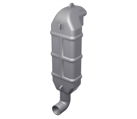
The photos, I hope:
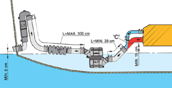
Peter’s drawing with my configuration added.
As you can see the gooseneck gets the exhaust run up high enough that a check valve is not required.
Peter’s drawing with my configuration added.
As you can see the gooseneck gets the exhaust run up high enough that a check valve is not required.
Last edited: