Fuel flow installation choice - hose or fittings

The friendliest place on the web for anyone who enjoys boating.
If you have answers, please help by responding to the unanswered posts.
Joined
Sep 25, 2018
Messages
542
Location
USA
Vessel Name
Aruna
Vessel Make
Kristen Yachts 50 Pilot House
I am about to install a fuel flow monitoring system and have a choice between two options that I'd like opinions on.

I have dual Volvo Penta TAMD 61A diesel engines with, of course, a fuel supply and return line for each. The system I will be installing will have a sensor in-line with both the supply and the return, otherwise it would be a pretty pointless system :)

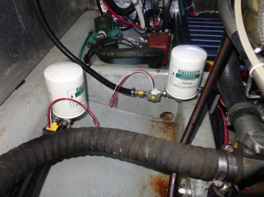
The majority of my fuel system piping is hard copper up until it bridges to the engine, in which case it is using 3/8" ID rubber hose for vibration damping, etc.

IMG_5510.jpg

I have two choices to install the sensors:

Rubber hose - the system came with very long hose barb connectors and clamps. I could cut the hoses you see above and insert the sensors there. Positives in this approach are that it is a relatively easy install, has a minimal amount of new failure points, and doesn't require anything other than what came with the product. Cons include cutting the hose and using clamps instead of fittings which is a failure point, plus the weight of the sensors on the hose.

Fittings - I also had NPT fittings included with the product. Where the hoses hit the copper in the bottom of the picture, I could get 2x adapters for each sensor which would attach to the provided fittings and the copper piping/rubber hose. Pros with this setup is that I wouldn't have to cut the hose, would easily be able to remove the system, and they would be relatively stable. Cons include having to find four (per engine - 8 total) new fittings to convert between the hose->sensor fitting and the sensor-> copper fitting, and all of the potential leak points introduced by the new fittings.

I like the fitting idea the most but I really don't relish having to have that many connectors. I am not going to chop off the end of the copper tube and change the fittings there, or change out the hoses so they match the various ends. That is far more intrusive than cutting the hoses, which I would prefer to do instead and if I want to longer term after I've proven the install, rework the hoses and fittings down to something simpler. That's not the plan for now.

Interested in any pros/cons I've not factored in for the two approaches above.
 
First, are the flow sensors orientation critical? The ones that came with my boat had to be horizontal.
Second, I wouldn't want them that close to the engine. Can you mount them further away where they would be out of the way?

Ted
 
First, are the flow sensors orientation critical? The ones that came with my boat had to be horizontal.
Second, I wouldn't want them that close to the engine. Can you mount them further away where they would be out of the way?

Ted

I've checked with the manufacturer, and the orientation is fine where they would be.

The only other break in the line is right after the fuel filter (Racor) and would require major surgery to get something into it, not to mention they're not easy to get to.

They would be tucked back away from anyone moving by them on both engines, the port one more-so. I definitely would like them somewhere else, but I don't really have any other places where there are breaks unless I want to create new ones.
 
First, are the flow sensors orientation critical? The ones that came with my boat had to be horizontal.
Second, I wouldn't want them that close to the engine. Can you mount them further away where they would be out of the way?

Ted

Hmm thinking a bit more about this, I could potentially just run new rubber only fuel lines from the Racor to the engine, and somewhere in the middle stick the fuel sensor. That would let me get it out of the way as well.

I'd have to look at the return to see how I could do that since I think it goes all the way back to the tank without any breaks.

After crawling around a bit, I found breaks in the return lines where it looks like they upsized the pipes leading back to the tank. Probably depending on which engine type/manufacturer got installed in the boat, these could be essentially universal in terms of the final run to the tank size.

So I definitely could replace the copper piping from/to the engine back to the Racor/return with fuel hose. Each run would be about 6-8' and then I could just cut the hose and use the hose barbs provided with the sensor, mount them on the wall near the filters, etc.

I've never run my own fuel hoses, so I'd want to learn how to put ends on and such so I can do it myself.

Still interested in opinions on the current setup as well.
 
Based upon my own experience, FlowScan was/is a pretty good product.
It went out of business a more than a few years back and recently bought out and restarted.

https://floscaninc.com/flowscan-products/

I had it installed on my N46, took less 4 hours.
 
Based upon my own experience, FlowScan was/is a pretty good product.
It went out of business a more than a few years back and recently bought out and restarted.

https://floscaninc.com/flowscan-products/

I had it installed on my N46, took less 4 hours.


Thanks. I’ve already selected a vendor. All of them have similar installs as they need a sensor inline.

I’m looking for opinions on whether to cut the hose (Floscan does this in many installs I’ve seen) or try to do something with flanges and tubing.
 
Once the sensor is installed, the electrical output can be routed anywhere.
 
Of your first two choices, I would put fitting on the sensor that match the male/female flare fittings at your copper to hose transition. When making additions like this, I really like installs that are easily reversible. Products need to be removed because they break, or don't work as expected, or simply require diagnostics. It's also an easy and clean install with minimal disruption to the rest of the boat. Those look like standard SAE flare fittings, so should be readily available. NEBAR in Ballard is a good source. And I don't see this adding any more new failure points than using the hose barbs. In my experience all your problems will be with the NPT joints, and if I'm following correctly you have them whether you use the hose barb fitting or some other fittings. RecotrSeal 5 is your friend for those joints, and I would definitely not use teflon tape.


As for replacing the whole run with hose, I'd probably only do that if I otherwise wanted to change the run to hose. And I don't like the idea of having a straight splice in the middle of a hose run if the sensor ever needs to be removed.

Thanks! I had been leaning towards the the fittings solution for the reason you brought up - easy to remove if there is an issue.

I've seen NEBAR before many times driving by, but never had a reason to stop. I also do have RectorSeal on board for some reason that I've forgotten, so I have that covered!
 
My only after market fuel flow experience was an airplane, not a boat, but for what it’s worth, here goes.....
I had my A&P install a fuel flow meter in my older Cessna due to the inaccuracies of the old level gauge.
He installed the sensor directly to the carb with a close nipple, then connected the original flexible hose to the sensor. It was a tidy looking professional job when done. The gauge was never as accurate as claimed, and ceased sensing after a couple of years.
I ordered the new sensor myself, and read the enclosed instructions! They said clearly that the sensor was to be attached to the airframe, and both the inlet and outlet should be flexible hoses. The new sensor was deadly accurate, and remains so for 10 years and counting.
Based on this experience if I put one in a boat I would:
Read the instructions if any.
Be sure the sensor is attached to a stable, vibration free part of the hull.
Use flexible hose in and out of the sensor if possible. I would have hoses made up with professional fittings to ensure longevity, and easy removal of sensor if needed. If layout demanded I attach one side of sensor to existing piping I would be sure that pipe is solidly attached to hull and not subject to vibration.
Just my thoughts based on an unrelated experience. I have a Willard with 500 gallon tanks and a single 1 1/4 gph Perkins, so have not given a moments thought to instantaneous fuel flow until now[emoji16]
 
I've seen NEBAR before many times driving by, but never had a reason to stop. I also do have RectorSeal on board for some reason that I've forgotten, so I have that covered!


It's an excellent place for all kinds of hoses, fittings, etc.
 
It's an excellent place for all kinds of hoses, fittings, etc.


Well unfortunately Nebar didn’t work out. Fantastic place. I spent about 30 minutes chatting with them about hoses and ends and exploring various options.

Unfortunately one end of my connector is JIS or Japanese standard, pseudo BPT. The other end is metric but has a weird reverse flare in it that they have rarely seen. Neither one is something they carry and would be a long special order if they can get it.

So my options now are back to:

Cutting the existing hose and using the provided hose barbs and clamps for both supply and return.

Running a whole new hose from the Racor filter to the engine for the supply and figuring out if I can replace the end for the engine connection (dubious). For the return I would have to either re terminate or splice into the copper or run a whole new rubber hose which would take days as it goes a very long ways. Same issue with engine side fitting - banjo like and probably would have to be reused and welded on to something new.

Final option is to return the whole product and not do the install which is also a possibility.

Sigh. Boats.
 
That sucks.


You might also check DiscountHydraulicHose.com They have a very good thread identification guide that has always been spot on, at least when I have actually take the time to measure and verify fittings in advance..... I have bought dozens and dozens of fitting from them of all sorts, including stuff I never knew existed.


The reverse flare might be BSP, but I expect NEBAR would have identified that. Kubota uses them on all their tractors and excavators and I bought a lot of wrong fittings before I finally figured out what it was. If I had only paid close attention to the identification guide in the first place......

Ah DiscountHydraulicHose.com looks interesting. I think I've found at least the JIC size, but not the perfect adapter I would want.

The one side is purportedly JIC, while the other side is metric. The JIC side is flared the way I've seen many other lines and connectors, but the metric side is the reverse, which I have not seen. Pictures below.

IMG_5552.jpg

Here is the metric end of both (one is for supply, one for return - different sizes of course). Note the bevel inwards.

IMG_5553.jpg

Top down view

IMG_5554.jpg

What we believe is the JIC side, which points towards the engine and goes into the black Volvo branded hose that in my original post.

IMG_5555.jpg

Close up view of the metric end with the odd flare.

The sensor end is an ORB #4 which does not come up much. I'm seeing if there is a better number for the #4 part.

I am finding JIC to ORB adapters, mostly for hydraulic and racing stuff, so I might be able to do that side.

It's the BPT or Metric side that I have no idea where to start looking. It doesn't look like a reverse flare, but maybe that's it?

The manufacturer of the sensors believes the hose may have a metal mesh in it, meaning I really shouldn't cut it and try hose barbs. So unless I can figure out some way of gender bending these adapters, I may just return the product and cross the project off the list.
 
If one joint is JIC, why not insert the sensor there? Put a JIC male on one end of the sensor, and JIC female swivel on the other end. Then just separate the original JIC joint, and insert the sensor.
 
Last edited:
BTW, you may already know this, but JIC and SAE flare can be very hard to distinguish, and unless a fitting is specifically made to work with both, they are NOT compatible. For maybe 60% of the fitting sizes, the threads are different so you can't even attempt to connect then. But for a handful of sizes the threads are the same and will lull you into thinking you have a match. I've been bitten by this a few times.


The difference is that the bevel on JIC is 37 deg, and on flare it's 45deg. So when you try to use them together the contact surface is a very small ring that doesn't seal well and doesn't hold pressure well. With matching bevel angles the contact area is the whole bevel surface.


I finally bought a cheap plastic gauge that has the two angles on it that you can hold up to a fitting. Even then it can be hard to tell which you have.
 
If one joint is JIC, why not insert the sensor there? Put a JIC male on one end of the sensor, and JIC female swivel on the other end. Then just separate the original JIC joint, and insert the sensor.

Yeah I need to find JIC in two different sizes going to an ORB #4 for both female and male. That would be a good option, but so far I have not found that quite yet.

I finally bought a cheap plastic gauge that has the two angles on it that you can hold up to a fitting. Even then it can be hard to tell which you have.

Oh that is a good tool. I have seen both and been bitten by both once. I am going to search for one and order it as I don't want to order a bevy of adapters :)
 
Have pity on the next owner. Don't jury-rig.

In many respects I really hate to say this. If you must get a custom made hose, get 2. One for now and one 'just in case'. Identify it with a tag and tuck it away someplace you wont forget tell the next owner.
 
Last edited:
Have pity on the next owner. Don't jury-rig.

In many respects I really hate to say this. If you must get a custom made hose, get 2. One for now and one 'just in case'. Identify it with a tag and tuck it away someplace you wont forget tell the next owner.

I'm not jury-rigging anything. I think you can see that from the questions I'm asking to try to put something together that is both supportable, removable, and reliable.

I don't think I am going to get a custom made hose, and if I do, I would definitely get at least one spare if not two. I already have 4x hoses in place (most likely original) that I can't get new versions of as it sits, which I don't like.

At the most, I would get two JIC to ORB adapters and leave everything else in place, only adding the sensor with the adapters.

Putting in all new hosing or changing things with a new hose would be more than I would want to do at this point, and would just return the product and move on.
 
How about putting the engine in flow sensor at the Racor, and the return flow sensor at the return fitting on the tank (or diverter valve if applicable).

I would then not hesitate to solid pipe on one side, and probably OK to have pipe on both sides as there would be no vibration. You should also be working with standard tube and fittings.

Flow into the pipe = flow out, unless of course something breaks!

Bill
 
Last edited:
How about putting the engine in flow sensor at the Racor, and the return flow sensor at the return fitting on the tank (or diverter valve if applicable).

I would then not hesitate to solid pipe on one side, and probably OK to have pipe on both sides as there would be no vibration.

Flow into the pipe = flow out, unless of course something breaks!

Bill

Interesting idea......

Returns are copper from the engine hose all the way to the back of the tank. They appear to have the same JIC connector that is used at the hose. And it's copper, and pretty tight, so I don't think I could stick a 3" wide sensor in between the pipe and the tank without bending something. I can disconnect them and push them back a bit, but not much more.

Same with the Racor - pipe comes out and does a 90 degree turn and is attached to stringers up to the engine. I might be able to detach and move it over a little, but not 3" wide. Pic below, sorry it's dark in there.

IMG_5556.jpg

I'd still have to come up with some adapters anyhow, and looking at the threads and sizes of things coming/going from the Racor, I'm betting it's the same standards as the adapters I'm working on at the engine. So I'd still need to find a male/female JIC/metric/whatever adapter set to ORB between some of the pieces.

I could chop the copper shorter and put new ends on, but that would require getting a flaring tool and such, and hoping I could re-use the fittings on the copper (should be able to) and find the right flare angle too.
 
I think this project is dead in the water.

After chatting with a local mechanic friend, visiting NEBAR and one other place, as well as talking with the manufacturer, the only idea we've come up with is to use the JIC portion of the existing adapter, and stick the sensor in between that and the hose going to the engine. This would be for both the supply and return.

My supply line is 3/4" or something close. I can't find my thread pitch gauge but I know where one is that I can use tomorrow.* Regardless, it is pretty large.*My return line is 5/8" or something close.*

The sensor adapter is 1/4" NPT. Most of what I can find online is NPTF which is better for fuel anyhow, but not 100% compatible with NTP without sealant.*Irritating that the sensor vendor doesn't use that. They also recommend just using teflon to seal it, which is a big no-no.

For the 3/4" supply line on the supply side I would need:

3/4" JIC female to 3/4" female NPTF
3/4" male NPTF to 1/2" female NPTF
1/2" male NPTF to 1/4" female NPTF
1/4" male NPT to ORB #4 (sensor)

On the far side of the sensor (engine side), reverse the process, but the JIC is male.

That's a total of 8 new fittings in addition to the existing fitting, or 9 new places that leaks could occur. And a ton of new weight to put between a hose and an existing line that really shouldn't have a lot of weight on it.*

The return line is 5/8" and I *might* be able to find a way to use one less adapter, but probably not.

Just seems like a lot of risk for what I'm getting out of it!
 
I see, you need a huge size difference between the two ends of the fittings. #4 ORB to #12JIC, or #10JIC.

So the issue really is that the sensor ports are tiny compared to the hose sizes. I remember dealing with this when installing a Maretron fuel flow device on a generator, and in that case I was only dealing with 1/2” or
#8 hose ends. I also abandoned that project, but for slightly different reasons.


Yeah that many bits and pieces make me nervous. Maretron’s sensor for my engine size has 1/4” NPT so at least I would be one connector less but still a decent amount.

Back to the drawing board!
 
I have flown lots of airplanes too and I think the fuel flow thing is a waste of time and money, it will not give you any useful information that you can’t get by just measuring your fuel.
 
I have flown lots of airplanes too and I think the fuel flow thing is a waste of time and money, it will not give you any useful information that you can’t get by just measuring your fuel.


I’ve had them on boats where they don’t matter - traditional trawler that is very predictable etc. After a year of usage on my current boat, I have very little concrete and repeatable info which is why I wanted it.
 
I’ve had them on boats where they don’t matter - traditional trawler that is very predictable etc. After a year of usage on my current boat, I have very little concrete and repeatable info which is why I wanted it.


Perhaps all you need to do is hook up the meter long enough to plot your fuel burn vs engine RPM. Short of re-propping, that won't change in the future.


Back when I was dabbling with this same issue, I was trying to get solid fuel burn vs load for a generator. The manufacturer only publishes two data points; 1/2 load and full load, and I was looking for a higher resolution plot of gph vs kw output. This was all in the context of trying to better understand fuel consumption to generate power via generator vs on-engine alternator(s). Bottom line is that I expected to install the metering system for a while to collect the salient data, then remove it.
 
This is a view of the in and out sensors of my self-installed Floscan before I ran and connected the wiring. This was the EASY part. Running the wiring to the console was a pure bitch. I am not a fan of hard piping for fuel systems in boats (removed as much as possible of those leaking fittings form my Grand Banks), and you see none here. I feel they are far more likely to leak than any hose and barb fittings, even if you never put the first hose clamp on the hose of these low pressure systems. In this case I just cut into the Racor to engine hose and stuck the ends into the barbs on the input sensor - five minute job. Because the hose on the return side ran high across the top of the engine bay and I wanted the return sensor down where you see it, I had to replace the entire run of hose with longer pieces to both sides of the sensor. Easy peasy.
 

Attachments

  • DSC01295.jpg
    DSC01295.jpg
    119.6 KB · Views: 31
Perhaps all you need to do is hook up the meter long enough to plot your fuel burn vs engine RPM. Short of re-propping, that won't change in the future.


Back when I was dabbling with this same issue, I was trying to get solid fuel burn vs load for a generator. The manufacturer only publishes two data points; 1/2 load and full load, and I was looking for a higher resolution plot of gph vs kw output. This was all in the context of trying to better understand fuel consumption to generate power via generator vs on-engine alternator(s). Bottom line is that I expected to install the metering system for a while to collect the salient data, then remove it.

Yes, this is part of my challenge. The previous owner gave me some very general numbers for GPH for the mains, but it has proven to be wildly above and below that by a small amount on the low side, and more than double on the high side. For a boat with a 300 gallon capacity, that means really frustrating planning for longer trips, and lots of stress. Most of the trips I am on involve 4-6 hour days of motoring, which can be a significant amount of fuel at 15GPH when you're expecting 7. That's almost 1/3rd of my capacity in one day, when I'm expecting much, much less.

I would like to find out why it varies so much, and the best way to do that is to have a meter and observe things, even if only on one engine, for a period of time. I have no problem adding one for a while and removing it if I'm worried, but even a short period of time with 8-10 adapters seems like a risk for the hoses and connections!


This is a view of the in and out sensors of my self-installed Floscan before I ran and connected the wiring. This was the EASY part. Running the wiring to the console was a pure bitch. I am not a fan of hard piping for fuel systems in boats (removed as much as possible of those leaking fittings form my Grand Banks), and you see none here. I feel they are far more likely to leak than any hose and barb fittings, even if you never put the first hose clamp on the hose of these low pressure systems. In this case I just cut into the Racor to engine hose and stuck the ends into the barbs on the input sensor - five minute job. Because the hose on the return side ran high across the top of the engine bay and I wanted the return sensor down where you see it, I had to replace the entire run of hose with longer pieces to both sides of the sensor. Easy peasy.

Nice setup. I wish I had hoses instead of copper piping, at least from the filters to the engines..

I did find joints in the return lines in the engine room late last night crawling around, and of course I have Racor filters that I could come off of for the supply lines.

So the safest approach would be to replace about 40' of copper for both engines with hoses from those points. The challenge would still be getting the right banjo adapters for the on-engine connection points, and dealing with the connection to the Racor and the supply joints - they are 100% going to be the same odd flare connections and sizes, so I would still need custom adapters or hoses.

Is getting the fuel burn information worth an investment of $400 in hoses and probably 3 hard days of labor? Potentially, or I could just continue using the old sight glass / pressure sensor tank monitoring method along with a spreadsheet.
 
Back
Top Bottom