Shore power issue

The friendliest place on the web for anyone who enjoys boating.
If you have answers, please help by responding to the unanswered posts.
Gkesden
Thanks I have found the answer I was looking for. The inverter switches both hot a d neutral. Shore power passes through inverter. inverter alone supplies both a d bonds to ground without shore power. Brain fart solved
 
Diver Dave,

I'm not following either. Assuming, which is a funny approach, that the vessel is wired correctly and has ELCI properly installed and assuming that the onboard ELCI isnt tripping but the shore GFCI is tripping, I'd have to hazard a wild guess of salt water or some other leak at the shore power inlet or power pedestal, at or near the fixture interface, e.g. cord, recepticle, associated wiring.

But, I just didn't follow :-(
 
For Diver Dave & others
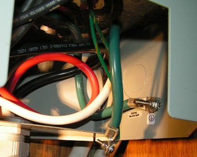
Below is a pic of the corrected connections, sorry the angle isn't good. The ground wire from the dock is connected to the IT shield, and the wire to the ship's ground - which is bonded to the neutral at the switchboard, is connected to the transformer case. There is no continuity between the incoming ground and ship's ground buss. In the previous pic all these are connected together, establishing a parallel circuit between GN connections in two places, the boat's switchboard and the dock distribution panel. There is no GFCI on the dock in this case. If there was it would have tripped because a portion of the load current is bypassing the device and unaccounted for. That's what the GFCI is sensing - any unaccounted current means power is going where its not supposed to go.

If a metallic inlet is used, it must be bonded to the incoming ground wire and isolated from the ship's ground buss. Otherwise the parallel circuit will be established. This installation is 100A and uses non metallic pin-and-sleeve connectors. The installation has a GF monitor on the secondary side which activates an alarm.

When installing an inverter, first identify all the neutral wires of the circuits that are to be inverter powered. This is usually most easily done by turning each circuit on, make sure there is some kind of load on each circuit, and measure the current on the hot wire with a clamp-on ammeter at the circuit breaker, then find the neutral wire on the buss with the same current. Install a new buss and connect all these to it, and wire the new buss to the inverter's N output. Connect the inverter N input to the existing N buss. When I say the inverter output N is not to be connected to the ship's N, I mean no external connection. The inverter will make the appropriate connections internally.

Hopefully these points are helpful. It's not practical to cover every detail that might arise and have a concise and readable post.

"This post is not intended to contain the complete solution to any particular issue"
 

Attachments

  • PICT0352.JPG
    PICT0352.JPG
    50.8 KB · Views: 342
I might have missed it because I'm cruising right now and only skim the previous posts, but old style reverse polarity lights if they didn't have enough resistance sometimes will trip these new dock. based gfi's
 
Today, I unplugged by galvanic display and that solved my issue for now....not a fix just a solution until I’m back to my dock.. thanks everyone
 
Today, I unplugged by galvanic display and that solved my issue for now....not a fix just a solution until I’m back to my dock.. thanks everyone

That's what I did too. And I bought a Hubbell tester for the shore power pedestal to make sure the power there has no problems.
 
There's an error in my last post, somebody can spot it before I reveal...?
 
There's an error in my last post, somebody can spot it before I reveal...?

When I say the inverter output N is not to be connected to the ship's N, I mean no external connection. The inverter will make the appropriate connections internally.

Did U mean G instead of N? My reading comprehension is no where near as good as my schematic reading ability. :dance:
 
There is no GFCI on the dock in this case. If there was it would have tripped because a portion of the load current is bypassing the device and unaccounted for.

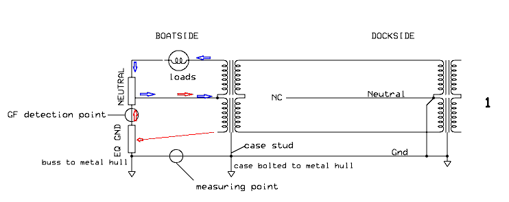
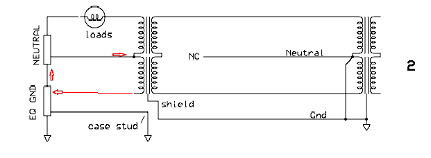
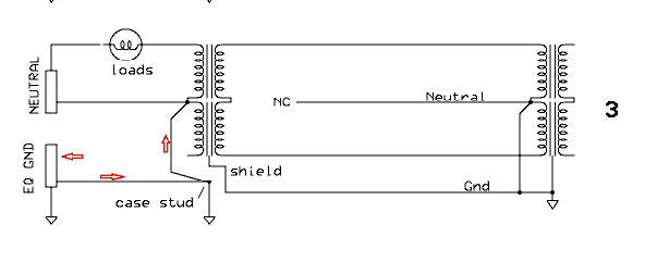
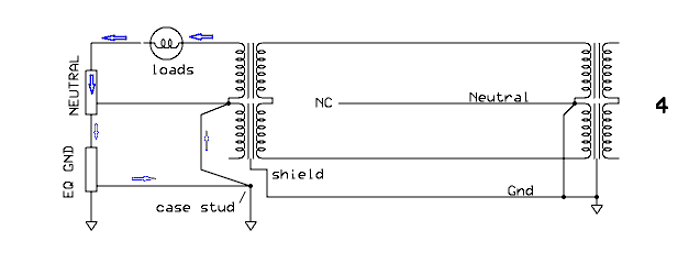
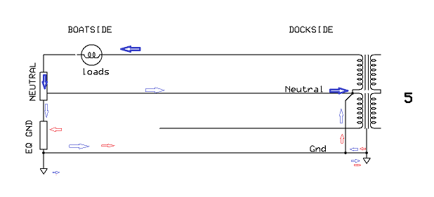
With an isolation transformer installed, the current would not go back to the dock, a dockside GFI would not trip. But now, there is a mystery since I sketched it out. I'm not quizzing, I don't know the answer. The current was there on the ship's side ground wire, gone with the connections changed, but where did it originate from? Five drawings here, only the essential elements with paths of load and fault current. Currents flowing through the water from elsewhere aren't being considered. 1 is the transformer connections as found; 2 is as changed; 3 is the same but as would be found on most pleasure boats; 4 shows the path of load current when there are two G-N connections - the crux of the subject I'm on here. 5 is with no transformer installed onboard.

The boat does have a Ground Fault detector and alarm, but it hadn't been working since(?) because the 24V fuse supplying it was blown.

I'm off to different parts soon and won't be back to this boat till spring, it will get some further investigation then.
 

Attachments

  • Fig1.png
    Fig1.png
    10.1 KB · Views: 37
  • Fig2.png
    Fig2.png
    6.5 KB · Views: 37
  • Fig3.png
    Fig3.png
    6.7 KB · Views: 31
  • Fig4.png
    Fig4.png
    6.9 KB · Views: 32
  • Fig5.png
    Fig5.png
    8.6 KB · Views: 40
It’s highly unlikely to be the galvanic isolator. You should contact a yard or marine electrician and have an ELCI master breaker installed. This breaker preforms the same function as the docks GFI. Once the ELCI breaker is installed you will know that your boat is not the issue.

In your case it might be as simple as a ground neutral bond but I have also see appliances that have internal failures cause this issue.

What he said. Unless you are a marine electrician, I would hire one. Hunt and peck for the source of the problem is a risky way to go. I have heard (and believe) that most boat fires are electrical in origin.
 
How did you build your gfci cord so you could test ?
great reply on your behalf. I have been struggling with this as more marinas get 'upgradded. in any case I would like to put one together and go through my circuits one by one. Thank you for the light at the end of the proverbial tunnel.
 
In the words of some famous person "it depends".
I am not an expert but I am interested in this discussion to continue as it surely is worth understanding. I have questions.
What is EQ GND?

..............The current was there on the ship's side ground wire, gone with the connections changed, but where did it originate from? From bonding to water, AC GND and DC GND?


Five drawings not able to follow change from 1 to 2 as it is now bonded to neutral which was agreed is wrong unless inverter driven

The boat does have a Ground Fault detector and alarm, but it hadn't been working since(?) because the 24V fuse supplying it was blown. 24V dc? would it not be ac powered

........
 
Without looking back at the thread, I think "EQ GND" means "Equipment Ground" or "Equipment Grounding Conductor (EGC)".

It connects non current carrying metal, e.g. conduit, metal enclosures, metal chassis, etc, to ground. This means that if a hot wire touches them it creates a short and quickly blows a breaker. This means that they can't stay hot until, for example, a human becomes the path between the accidentally hot metal and ground -- a Zzzzap! event.
 
How did you build your gfci cord so you could test ?
great reply on your behalf. I have been struggling with this as more marinas get 'upgradded. in any case I would like to put one together and go through my circuits one by one. Thank you for the light at the end of the proverbial tunnel.

I built it about 30 years ago for a different purpose. It worked well for testing for GFI problems. It is just an extension cord with the female end cut off. An electrical box with a GFI breaker and an outlet. I use a 30 amp to 15 amp adapter to plug the boats shore power cord into the box with the adapter. Then turn on one circuit at a time. When you hit a problem circuit the GFI will trip. My boat has 2 30 amp inlets and they had commingled all the neutrals on one bus bar. The first thing I had to do was break the neutrals into 2 bus bars. If I were going to make a test cord now I would use an old 30 amp shore power cord and a 30 amp GFI breaker along with an L5-30 outlet in the test box instead of a 15 amp GFI. Then I could plug in a whole 30 amp inlet and do the testing at one time instead of circuit by circuit.
 
I saw the mention of an isolation transformer which might help, but you do have a problem somewhere in your electrical system, and as was also said, most boat fires are electrical.

Find the problem first, absolutely, utilizing an ABYC electrician. This is not to be done by a home electrician, period.

After you have that sorted out, then put an ELCI in you boat. It is less expensive, lighter and will solve future problems.

Since you have a 30A boat you probably have a separate A/C plug as well. Get a dual ELCI and connect both.

I'm not an electrician but I have had experiences with shore power faults. You tell a marina that a power issue is with their system, they'll say, prove it. With an ELCI, you tell them you have 1 installed, you've proven it.

I have had numerous experiences where our ELCI showed, it gives a reverse polarity message, that there was a shore side problem. We just pick another pedestal.

If you are an electrical type person, Google reverse polarity and read all about it.

When I pull into a marina I know I'm not going to have any issues. It's a good feeling.

Good luck.
 
Have Marine Electrican coming next week, thanks everyone
 
Following. We have a single 30amp shore power inlet, that goes to an isolation transformer. Our 30-yr old f/g boat (from Asia, with a 3-wire, 230v AC system, and a factory-installed bonding system) does not have a GFIC installed, so based on written advice I did not jumper the neutral and ground on the transformer output. The Reverse Polarity light illuminated and would not go out until I installed that Neutral-Ground jumper in the transformer....required per Victron IF a GFIC is installed. But ever since the transformer was installed, I keep losing my bottom paint for about a foot around my thruhulls. Still trying to find the cause!
 
How did you build your gfci cord so you could test ?

They sell GFCI extension cords at Amazon and most big-box stores. Also, small plug-in GFCI adapters. I have one in my electrical tool box.

Don't let all this talk scare you. None of this is rocket science. Basic boat wiring is pretty simple. Yes, it is tedious figuring out where all the wires go, checking them all, and removing and re-installing existing stuff.

Boats were historically wired with neutral and ground connected, with very little negative impact. Just like my house was originally wired with knob-and-tube wiring and nobody died from it.

But in both cases, times have changed and there's now a safer way. Even if the relatively small safety benefit isn't worth it to you, having a GFCI-ready boat is becoming a necessity. Finding and eliminating ground faults is now worth the effort, and something any reasonably capable DIY'er can handle.
 
What he said. Unless you are a marine electrician, I would hire one. Hunt and peck for the source of the problem is a risky way to go. I have heard (and believe) that most boat fires are electrical in origin.


This may help unserstand the threats....


https://www.boatus.com/magazine/2018/april/analyzing-electrical-fires-on-boats.asp


We analyzed five years of BoatUS Marine Insurance claim files and found that the boat's DC electrical system — batteries, lights, wiring, and so on — cause more than a third of all fires. The boat's AC shore power system contributes to another 9 percent. More than half of DC electrical fires, or 19 percent of all fires originating on boats, were associated with either the engine or the batteries, both of which tend to be in the engine room.
 
Following. We have a single 30amp shore power inlet, that goes to an isolation transformer. Our 30-yr old f/g boat (from Asia, with a 3-wire, 230v AC system, and a factory-installed bonding system) does not have a GFIC installed, so based on written advice I did not jumper the neutral and ground on the transformer output. The Reverse Polarity light illuminated and would not go out until I installed that Neutral-Ground jumper in the transformer....required per Victron IF a GFIC is installed. But ever since the transformer was installed, I keep losing my bottom paint for about a foot around my thruhulls. Still trying to find the cause!

Do you have copper anti-fouling paint?

It could be it was applied directly over thru-hulls without priming to isolate it.

Then burning could be from galvanic action related to your zincs.

Being over zinced could make it worse -- you can uae a meter to check.

Also, is there an SSB or HAM radio grounded to than they-hulls?
 
Last edited:
What I have seen with boats from the 80s with 2 shore power inlets is that they put all the neutrals on one bus bar. It worked then but it won’t work now with the newly wired docks.

My 85 IG has neutrals and grounds on one bus bar. Will trip latest marina breakers. My current marina hasn't upgraded yet, neither have I. WInter project: Install new bus bar. Route all panel neutrals to bus bar and then connect incoming neutral to bus bar.
 
Thanks, gkesden. We do use copper-based antifoul (International Micron 66). And since we've gotten to the Caribb, we have not been able to find the hull zincs with the rubber boot on them....and I've noticed the contractor who applied the bottom paint slopped it around those 2 zincs pretty well. We just resplashed, and I installed 2 new hull zincs that I painted the bottoms and sides with rubber paint (the tool handle stuff). And I know the thruhulls were not isolated with separate primer. so far....so good--but we've only been in the water 4 days now!
 
That's a new one on me...rubber boots on zincs or painting them with non-conductive pant.


Where did you hear either of those is proper/normal??????
 
Cant saybIve heard of boots or rubber paint, either. I'd be especially careful with rubber boots -- or the zinc might not contact the bolts to get the the bonding system.

I'd also be concerned isolating a zinc with rubber paint could reduce area and make it less effective in an imperfect world.

Mostly I think the "paint peeling around thru hull" problem is solved by priming and making sure things arent super crazy wild over zinced.
 
Well, they are "normal" everywhere we were in Asia, and most places in the Medd. Here in the western world I have not seen them, but have seen "zinc rubber pads" for mounting the hull zincs on. The idea behind them, as far as I know, was to insulate the zinc from slopped-over, highly conductive(copper laden) antifoul paint. The zincs are held in place by 2 center bolts, the other end of which (inside the hull) are connected to the bonding system; current flows from the bonding system to the bolt to the zinc...and not thru the antifoul paint to metal holidays(P strut, bronze thruhull, etc. As it's been explained to me....I'm no expert , but itis real!
 
Boatcrazy,

The theory makes sense. Just never heard of it. Maybe more common in warmer waters or something.
 
Well, they are "normal" everywhere we were in Asia, and most places in the Medd. Here in the western world I have not seen them, but have seen "zinc rubber pads" for mounting the hull zincs on. The idea behind them, as far as I know, was to insulate the zinc from slopped-over, highly conductive(copper laden) antifoul paint. The zincs are held in place by 2 center bolts, the other end of which (inside the hull) are connected to the bonding system; current flows from the bonding system to the bolt to the zinc...and not thru the antifoul paint to metal holidays(P strut, bronze thruhull, etc. As it's been explained to me....I'm no expert , but itis real!

I can see the value in mounting a transom zinc on a rubber pad, but there is nothing on internet about painting all sides and front with rubber. Rubber should not conduct electricity, the whole basis of electric flow from more valued metal to sacrificial anode.
 
Just to clarify....the zincs I'm referring to are rectangular, typically about 3"x6" and about 2" thick, and have an exposed steel center portion with 2 bolt holes. They fit into a shallow well molded into the hull. The rubber "boot" only covers the outside portion of the back side and approx 0.5" up on the 4 sides. And, as I've written and had it explained to me, the idea is to insulate the back and sides from slopped over antifoul paint in the zinc well. There's still plenty of zinc surface exposed to seawater, and nothing interferes with the bolt/zinc connection. Enough said!
 

Latest posts

Back
Top Bottom