Star-Lord, Electric Trawler Conversion

The friendliest place on the web for anyone who enjoys boating.
If you have answers, please help by responding to the unanswered posts.
switching to single inboard

The project is still moving forward. I have been working very hard below the waterline to get the boat floated to my dock for the inside electric refit.

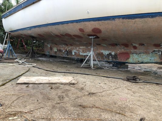
I have a more than 80 plate size blisters ground and feathered out that still need to be glassed over. The hull is ground down all the way to bare skin out mat.

Probably next month on the blisters. I am busy doing other things to let them dry out as long as possible.

I also removed the all the running gear for better sealing of the new barrier coat underneath. In the process I realized what sad condition they were in. One of the shaft logs was actually cracked and had been refit at least once before. There are new mounting holes adjacent to the original holes perhaps compromising structure in the hull.

This week I decided to discard the twin screw set up and go to a single shaft run down the center of the keel. I am in the process of designing this new set up. One of the previous posts suggested making the boat a single inboard and now I agree that this may be a good idea. Especially since the boat also has a bow thruster.

I realized that the boat had the waste water holding tank just dumping into the back half of the keel. The back half of the keel had a bulk head and cap to form the tank. There was no separate liner for the tank. The waste water was right up against the hull. Not good.

I removed the make shift holding tank and cleared out the keel yesterday. Very disgustingly nasty job. Now the keel is open for me to install a stern shaft tube.

I am planning to glass in a fiberglass stern tube with cutless bearing instead of using a bronze housing and tube set up. Researching the pro and cons of this idea right now. All opinions and advice is welcomed. My first step is to order the stern tube so I can dry fit it.

Sorry I don't have pictures right now. I will add some later.
 
I did a single engine install and used FG tube glassed directly to the hull penetration. It worked out very well. Had an SS strut fabbed by a local welder. Made bushings out of PVC (on a lathe) that held shaft, strut and tube in exact position while glassing tube to hull. Once all set in place, pulled shaft and installed cutlass bearings, alignment was perfect.
 
This week I decided to discard the twin screw set up and go to a single shaft run down the center of the keel... Especially since the boat also has a bow thruster.
Most mortals would be afraid to tackle such a major project. I think you made an excellent decision, Quill [emoji846]
 
On our 90/90 I was able to install a stern bearing that contained about 18 rings of packing , that was both bearing and rear packing seal.

A 19x13 Two blade prop makes loads of side force.

Works quite well and we were able to replace the packing on a cruise ,after a decade or so, with no haul out.

At the time the boat was built modern packing was not available so a grease line from under the galley sunk had a cup that required a turn or two to soip drips when in port.

Today with modern packing the grease is no longer required.
 
blister repair

Update on the blister repair with some pictures.

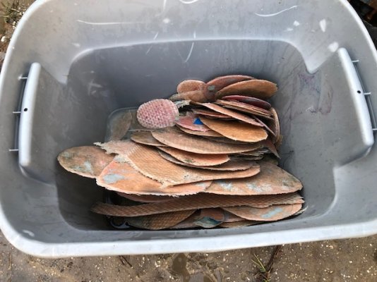
I have located and removed all the delaminated sections I can find. The total count is over 80. I am quite disgusted with this situation but I am going to continue with the experiment.

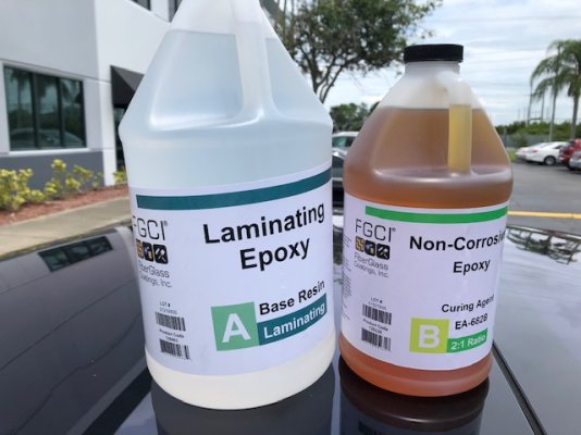
The delaminated sections are always down to the same depth of fiberglass layer about 1/8" thick. All the sections have been exposed and feathered. Next month I will start laying in two layers of 1708 fiberglass with epoxy resin.

IMG_1814.jpg

IMG_1835.jpg

IMG_1840.jpg

IMG_1836.jpg
 
That was a major hull construction failure there, an entire thick outer skin layer did not bond well? or is it just bubbles of blisters. I wonder if the rest of the currently bonded areas are going to delaminte too. I have seen hull peelers in action, they strip off entire layers of gelcoat and glass., which might simply be best to strip off the entire failing layer and glass on another new layer?
 
Single Screw Conversion

Unexpectedly I decided to convert from twin inboard props to a single keel mounted propeller.
I may be sacrificing some maneuverability but hopefully gain some efficiency.
Also the running gear was is sad shape and I didn't want to spend the money on new hardware.
The single drive train will also reduce my work load on the electric motor mounting fabrication and electronics once I get to that phase of the project.

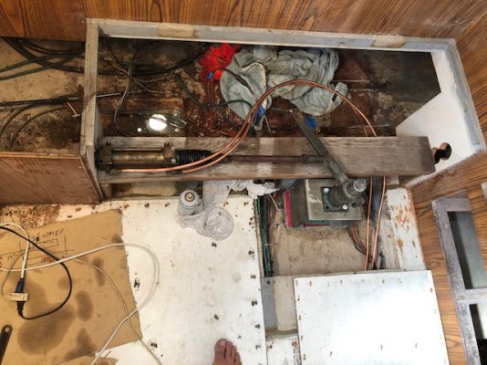
This is a picture of the engine bay.
To the left of the picture is towards the back of the boat.
I have already removed both of the diesel engines on either side.
The new electric motor will hang lower in between the bunks down in the hollow keel.
The new shaft will intersect the two cross members which is where I will mount a thrust bearing to accept the shaft flange.
My plan right now is to use the wheel hub bearing from my donor Prius as the coupler for the automotive CV joint and propeller straight shaft.

IMG_1859.jpg

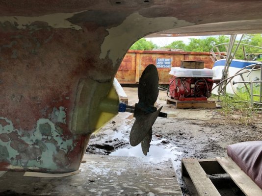
Here is a picture of a mock-up of my propeller mounting.
The shaft angle is set to a 2"rise (9.5 degree).
I am thinking a 4 blade 22x18 prop may work for my setup.
I also need to decide how close to mount the rudder.
IMG_1861.jpg

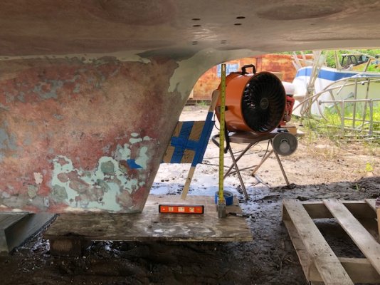
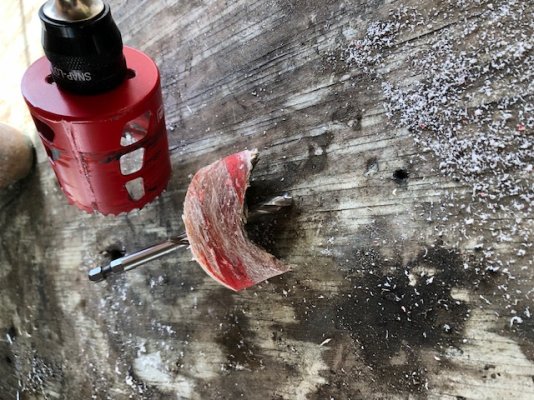
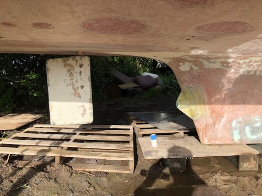
Yesterday I drilled a 2.5" hole in the keel to insert my new stern tube.
Hopefully at the correct angle.
IMG_1862.jpg

The plug is an inch thick.
I also see signs of the dreaded hydrolysis in the cross section.
IMG_1863.jpg

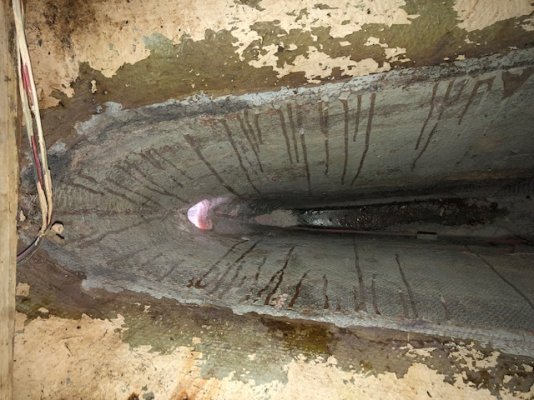
Picture inside the aft part of the keel showing the new hole.
This is where the waste water used to be dumped right up against the raw fiberglass.
IMG_1864.jpg

Picture of the stern tube section I bought.
2.5" OD 1/4" thick G10 tube.
I am now contemplating the best way to glass this in.
IMG_1866.jpg
 
It's not going to be easy to glass the tube from the inside of the hull. Can do it all from the outside and then install a shelf a couple feet fwd of the keel end and glass tube to that.

Save mounting and glassing tube for after you get the drive motor mounted, that way shaft and tube fitment can be dead on.

You can also extend the tube somewhat aft of the keel, and build up a good bit of glass to fair the deadwood and get prop away from the turbulence.

The last tube I bought had a very precise ID that the bearing pressed into very snug. Hopefully yours is similar.

You will need a remote mounted thrust bearing on fwd end of shaft to avoid thrust loading the Prius tranny.


I agree.
Here is kind of what I am thinking. (Not to scale)
IMG_1867.jpg
 
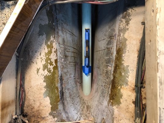
Stern tube dry fit

Things are lining up pretty good in the dry fit.
The shaft in the picture is protruding more than it will be until I drill a hole in the forward bulk head for it to pass through.
The shaft length seems like it will work well for mounting the thrust bearing on the forward end.

The tube is longer than is needed but works better for alignment this way.
I have a bushing on each end keeping the shaft aligned inside.
Once it is glassed in I can cut the tube to length.

It was suggested to build a shelf under tube prior to installing. I marked my locations for this step. I am also going to file some groves in the keel hole for injecting some epoxy.

IMG_1869.jpg

IMG_1870.jpg
 
Wow. Looks good. Plenty of side support to wedge the shelf in too.
 
You might find this product helpful, I have had great results ith Orange

Chockfast Products - ITW Performance Polymers

https://itwperformancepolymers.com/products/chockfast
The Chockfast range of high-performance epoxy grouting and chocking compounds provides precise and permanent alignment of all machinery, resistance to ...

Chockfast Orange

CHOCKFAST® ORANGE was developed as a chocking or ...

Chockfast Red HF

CHOCKFAST® Red HF Epoxy Grout is the next generation ...

Chockfast Red

CHOCKFAST® Red is a three-component, high strength, 100 ...

Chockfast Blue

CHOCKFAST® Blue is unexcelled under heavy reciprocating and ...

More results from itwperformancepolymers.com »
 
stern tube glassed in

I got the stern tube glassed in.
It seems very strong.
I don't have a picture with me inside the keel but the support is substantial inside.
I built a shelf under the tube and filled it solid around the tube with epoxy.

On the outside I used 4 layers of 1708 on each side. This adds about another 1/4" around the tube with a 1/2" thick angle support.

The new cutlass bearing seems like it will be a snug fit. I didn't press it all the way in yet.
I need to drill and tap a couple of set screw holes first.

Do I need to tap a hole and install a tube inside near the stuffing box to feed water for cooling the cutlass bearing?
I have seen this on some systems.

Next is the rudder mounting.

IMG_1880.jpg

IMG_1881.jpg

IMG_1882.jpg
 
"Do I need to tap a hole and install a tube inside near the stuffing box to feed water for cooling the cutlass bearing?
I have seen this on some systems."

Probably not at your speeds.

Some stuffing boxes need cooling , but a std unit with modern packing does not.
 
It is good to have some water flow through the cutlass bearing. Mainly to flush out any sand or wear products. Most use a hole drilled fwd of the bearing venting the tube volume to the sea. Normal boat motion provides some flow.

It does not look like the tube extends far enough from the keel to do this. And I doubt you are having any forced cooling water with your propulsion system. So you will likely do without. Probably no big deal.

You could probably tap into a through-hull fitting and connect to a tap in fwd part of the tube. Probably not worth the trouble.
 
rudder dry fit

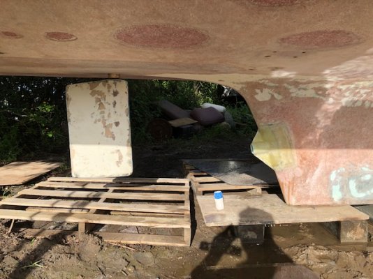
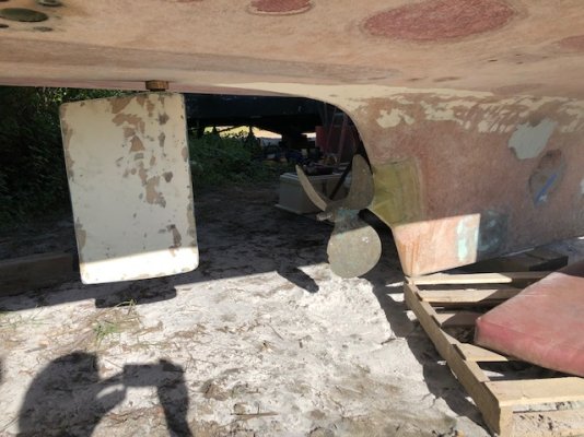
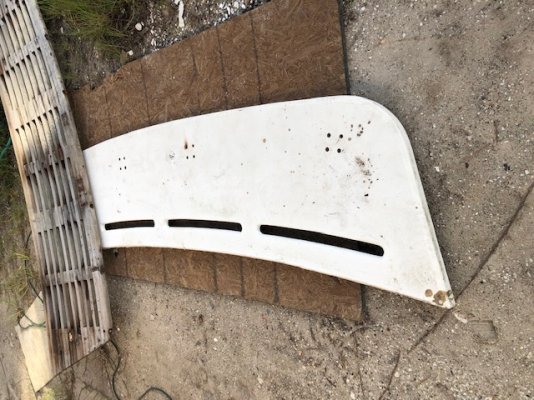
I made the new pad for the rudder hardware and did a dry fit yesterday.

I wanted to move the rudder closer to the prop for better torque vectoring at low speed but the hardware would have intruded into the aft cabin too much.

I think this will work. May not have the greatest maneuverability but I can tweak things in the future. ie bigger rudder or stern thruster

I will have to drop the rudder or insert the shaft from the inside of the keel. I did not put an offset in the alignment.

Now I need to start patching the blisters and filling the unused running gear through hull areas.

rudder dry fit.jpg
 
Even just eye-balling it, it appears that you're going to have very poor performance from that rudder, especially considering that you'll likely be focused on slow speed cruising.

Is that just one of the previous rudders from when your boat was a twin? Perhaps think about doubling the size of that rudder, making sure it is airfoil shaped, add a fish-tail wedge to the trailing edge, and possibly running a steel support skeg from the keel to support the bottom of the rudder post (like a deep, stainless C-channel).

Easier to do it now rather than later when you have to haul the boat back on land again with all those costs.

However, you may wish to visit boatdesign.net/forums and ask for some assistance with calculations for rudder size and also some feedback on how far back it is located.
 
Last edited:
"I will have to drop the rudder or insert the shaft from the inside of the keel. I did not put an offset in the alignment."

On many rudders a hole is drilled to allow the shaft to be fitted with the rudder in place.

A large Zinc can cover the hole , if you think it matters.
 
I'm no expert in rudders, but have set up quite a few. My gut feel is the rudder being well aft of the wheel will not be a big problem. The prop wash will hit the rudder whether it is one foot or three feet aft. Might have some issue in zero speed maneuvering, but once the wash does hit the rudder, you will have an effect.

I'd say continue as planned, but build in some contingency to move rudder should steering suck massively.
 
aft helm station

This weekend I mounted the helm from the removed flybridge above the aft cabin. I live in Florida and it will be too hot to only have a lower station inside the saloon. Later on I will likely build a dash board for instrumentation. The helm mount is just a left over piece of stainless from the unused rudder hardware.
From this station there should be fairly good visibility across the top of the solar panel array and down each side deck. There is also room for some custom seating.

IMG_1895.jpg
solar panels config1.jpg

The new rudder location is forward the original ones by a little over a foot. I repositioned the hydraulics under a bench seat in the cabin. I still have to reinforce the structure and plumb in the relief valves and reservoir.

IMG_1888.jpg
IMG_1893.jpg

I am probably going to stick with the undersized rudder for now to continue with the experiment.

I am only doing minimal items in order to get the boat in the water and towed to my dock for additional mechanical work.

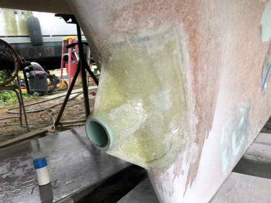
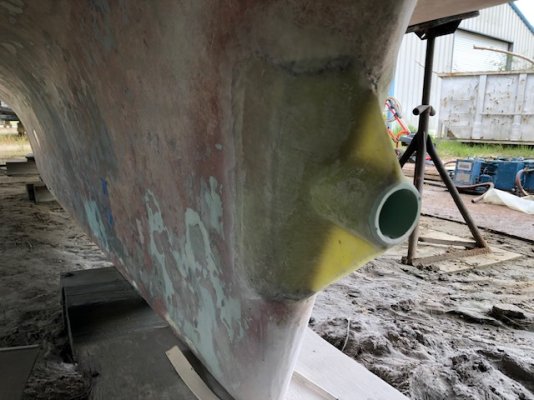
I also glassed over the twin shaft log holes. I put 10 layers of 1708 and used epoxy resin. I put 3 layers inside and 7 layers outside. My fiberglass skills are improving.

Getting ready to tackle the blister patches. I am planning on using two layers of 1708 for each.
 
getting ready for bottom paint

I have all the blister patches glassed in. I used two layers (sometimes 3 layers) of 1708 and epoxy resin in each patch.

I should finish fairing this week using Total Boat fairing compound.

I ordered 8 gallons of Interlux 2000e epoxy primer today. Hopefully paint in a couple weeks.

I am also enlarging my rudder. At least by 50%. I will show some pictures for this later. Since I changed from twin screw to single screw using only one of the two original rudders may not be enough surface area.

It has been a back breaker so far. I think I have identified several areas for the water intrusion that are being remedied. Perhaps I have a 50% chance of arresting the blistering problem in the future.

I also scored some props and a swim platform from another scrapped boat in the yard. I already mounted the swim platform. It should work nicely.
swim platform.jpg
props.jpg
The props are 23x22 with a 1 3/8" shaft. My original shaft was 1 1/2" but I also got the shafts and packing gland from the donor boat. They were in pretty good condition.

Napkin math for 22" pitch means 48rpm per mph without considering slippage. I expect to be in the 300 to 400 shaft rpm for 5 to 6 mph. This happens to be a good rpm for my motor and gear box also.

I am glad I got both the left and right hand props. I don't know which orientation I will be mounting my electric motor and transmission and it does have a preferred forward rotation in the gear box. Having both props allows me some flexibility in motor orientation.

I also cut a section of the 1 3/8" shaft to act a dummy shaft for the initial launch. I can then get the full shaft cut to length and keyed once I mount my motor. I will then attempt to swap the shafts out in the water without sinking.

My goal is to float the boat next month and tow to my dock for topside and interior projects.

This is turning into a life long hobby but one of my first projects will be to mount some of the solar panels even before I mount the motor. With some panels mounted I can experiment with my inverter designs.

Thanks
Jeff
 
Barrier Coat and Larger Rudder

I finished putting my barrier coats of Interprotect 2000E.
After I put the first coat on, it became apparent that I needed to fill and fair the entire hull. I knew there were pin hole voids and grinding gouges but I was hopeful the paint would hide them. It did not.

The fill and fairing was a big job and the boat seemed to get bigger as I went.
Really looks nice now after 4 more coats of Interprotect.
A lot of sins covered by the paint.

I also installed the modified rudder. I added about 50% more surface area with fiberglass tail in a tear drop profile for less water resistance.

I now need to apply another coat of Interprotect followed by a coat of anti-fouling while the primer is still tacky to avoid sanding. This stuff dries so fast I am not sure how I am going to pull this off.

rudder dry fit.jpg
larger rudder.jpg
 
S.L. your progress is fantastic.

Looking at the rudder, even though it is larger, it seems that perhaps only half of it is directly in the slipstream.

Perhaps consider adding a couple of bent plates to the trailing edge to create a fish tale. That should help demonstrably with slow speed maneuvering.
 
Does not look like an optimal rudder for this app, but rudders are easy to modify later. I'd roll with it as is. It might work fine.

I've never had a problem putting antifoul right over fully cured interprotect. Maybe I was not following the instructions, but I did not have any problems with antifoul adhesion.
 
Really coming along nice, SL. I'm looking forward to hearing about the first few test runs.
 
it is floating very high

I finally put the project in the water.:D

I'm getting things coordinated to tow it 20miles to my dock.

I removed all the old rusted kitchen appliances which was a few hundred pounds.
(refrigerator, washer and dryer, trash compactor, dish washer, ice maker)

I also siphoned out 250 gallons of fuel and emptied the water tank. Both of these tanks are molded into the keel forward of where the old engines were.

The fresh water (not so fresh) had a salty taste to it. I don't know how old it is. I don't know if it was sea water or something else causing the salty taste.

Without engines and everything else, the boat weighed 18000# according to the lift gauges.

You can sort of see in the picture that it sits very high in the water. The bow thruster is only half way submerged.:eek:
StarLordWorkDock.jpg

Adding weight down will be essential especially with my plans of adding the solar panels up high. I found some specs for the GulfStar 43 motorsailor which is the same hull design. It showed 3500# of ballast.

The latest sketch of my solar array plans uses 18 of the sunpower E20-327 series. I saw these used on ebay for around $100 each.

I mounted the helm above the aft cabin and plan to leave an opening in the solar array in that area.

StarLord solar sketch.jpg
 
You miight want to get some ballast down there in the bilge!! Stability is in question with all that weight pulled out. How dicey stability is impossible to tell over the net. Get some weight down low and leave it there until you start adding batteries. They make good ballast.

Any factory ballast in the keel/bilge?
 

Latest posts

Back
Top Bottom