Fixing a leaking 70's era Capilano 250V Helm steering station

The friendliest place on the web for anyone who enjoys boating.
If you have answers, please help by responding to the unanswered posts.

sbman

Guru
Joined
Jul 25, 2017
Messages
828
Location
USA
Vessel Name
Second Chance
Vessel Make
42' Uniflite Double Cabin
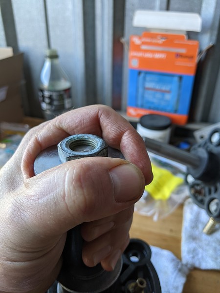
Both helm pumps on my Uniflite were weeping hydraulic fluid when I purchased it. After researching, the Teleflex Capilano 250V was discontinued in 1987 and Teleflex was aquired by SeaStar at some point. The new helm station was introduced as the 1250V in that time frame.

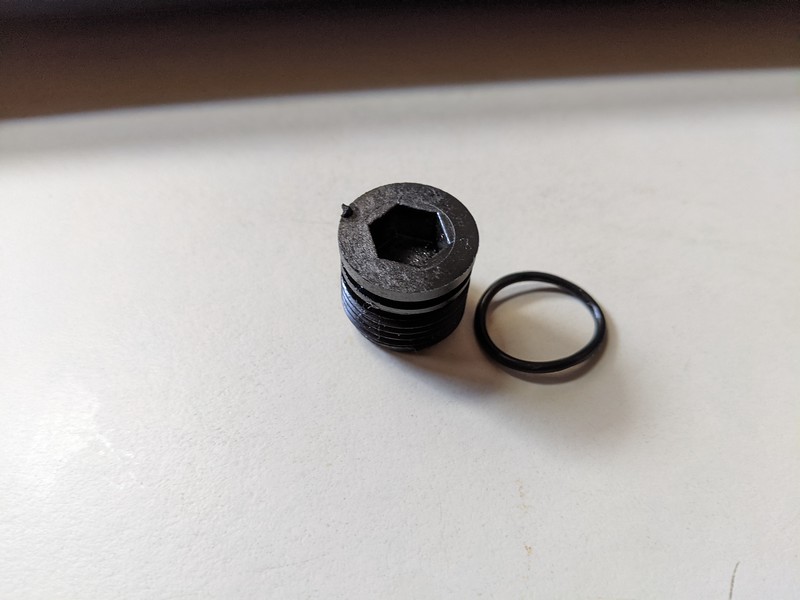
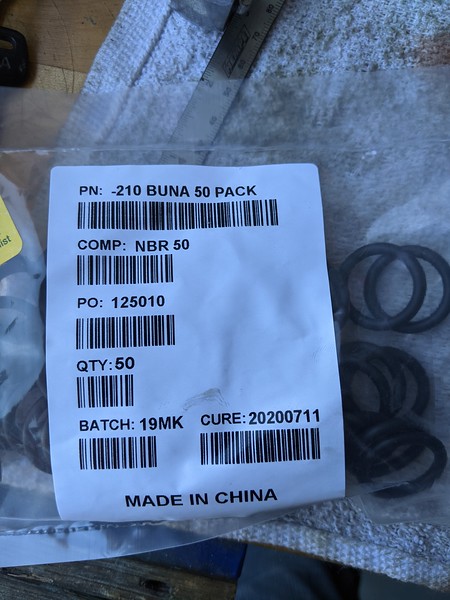
I emailed Seastar and asked about parts for the pumps. I was told there is a seal kit for the 1250V that would have the proper seals to reseal the pump, so I ordered it up. The kit includes a number of o-rings, a paper gasket and a plastic faceplate for the front shaft seal. To sum up the product, the kit didn't fit. Details to follow.

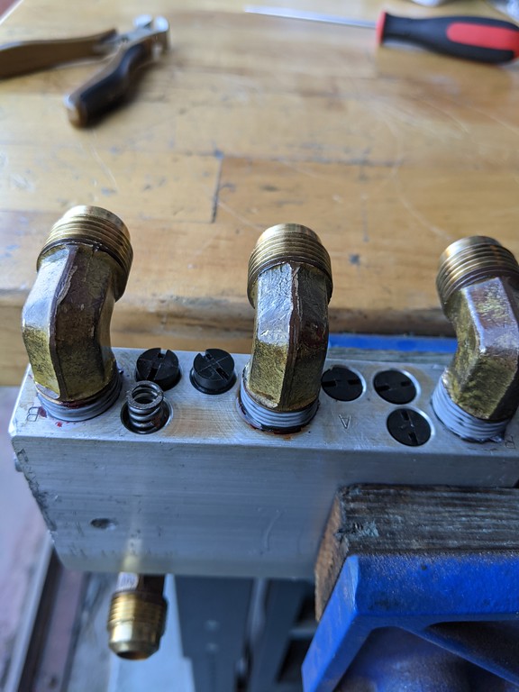
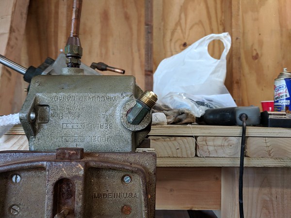
The 250V in it's native environment:

i-MK3jm86-L.jpg


The seal kit provided by Sea Star

i-wsQdGBn-L.jpg


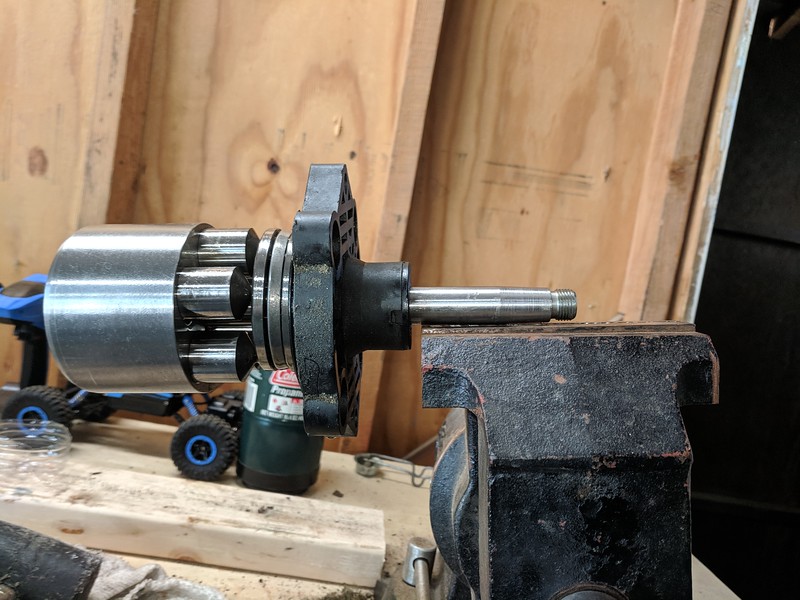
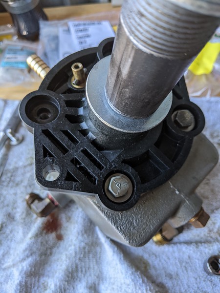
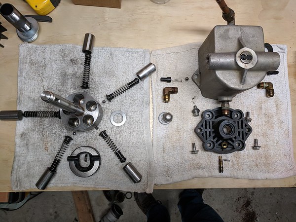
The 250V does not have a shuttle valve in it. This is a separate unit on the older systems that is in a unit called a 'Uniflow' valve which is located near the steering ram. It does not have a removable back portion as shown in the diagram for the 1250V, and also does not have the same type of check ball valves on the outputs.
 
After removing the unit from the boat, the first step in disassembling it is to isolate the shaft/pump and it's internal springs. To do this, I used a 3.5" long piece of black pipe and a stack of 3/4" washers. Put this on in place of the steering wheel and tighten the nut down finger tight. Now remove the four bolts on the front cover and gently pry the cover off. It has a good amount of resistance due to the o-ring that seals it. Once you get it loose, the entire pump shaft lifts free of the housing with the front cover still in place.

i-wJ2MrJS-L.jpg
 
Next up is the remove the key from the shaft so the front cover can be pulled off. If it gives you trouble, clamp it in your vice really tightly and then you can rock the shaft off the key.

i-8g4JDGd-M.jpg
 
A woodworkers vice helps to hold the body while removing the fittings on the outputs. I clamped it up here and used wrenches to pull off the bronze output fittings so that I could clean the output check valve assemblies. At first I also thought there were o-rings in here to replace, but there are not on the older units.

i-VPWmSbQ-M.jpg
 
Once the keyway is out, it's easy to disassemble the rest of the pump by just removing the parts by hand. I laid them out in the locations they came from to keep track of the assembly.

i-W24bzFh-M.jpg
 
The adjuster on the front cover allows adjustment of the 'boost' of the system and changes the number of turns lock to lock. This adjuster is a common leak point. It has an o-ring installed on the shaft that needs to be replaced. To remove the adjuster, you have to drive out the roll pin on the shaft and then screw the shaft INTO the front cover, and it comes out the back.

I used a roll pin punch to remove it. This type of punch has a centering pin on it that keeps the punch centered on the pin. Setting it up against the vice jaws partially opened and gently driving it out was farily easy with this tool.

After changing the o-ring on the adjuster, screw it back in and drive the roll pin back in place. I used a roll pin starter driver. These are commonly sold as 'gun' tools.

i-3tj2LW2-M.jpg
 
There are only three o-rings to change. I found that the o-ring provided by sea star for the front cover was not the correct o-ring. They provided a -152 o-ring which has an outside diameter of 3.443". However, the opening in the body of the pump is exactly 3.500". The provided o-ring didn't seal at all. The one I removed was obviously a different o-ring.

I decided to return the sea star kit since the primary o-ring wasn't the right size. I ordered the three o-rings I needed from McMaster carr.

Front cover o-ring : https://www.mcmaster.com/9452K165 (-236, Buna-N Dur 70, 3.512" O.D.)
Steering Shaft o-ring : https://www.mcmaster.com/9452K29 (-210, Buna-N Dur 70)
Adjuster o-ring: https://www.mcmaster.com/9452K18 (-010, Buna-N Dur 70)

The upside of going this route was that two helm kits from sea star are $100. I'd expect to get the right parts in it, especially for the price. From McMaster, the three o-rings I needed were $22.51 plus shipping. This is enough o-rings to do 50 helm stations, and is the minimum quantity.

I did call sea star and the tech I spoke to had no idea why the o-ring wasn't the correct one. It was definetly the o-ring specified in their parts list, but that doesn't fit my pump. I think that the early pumps had a larger diameter bore than the later pumps, but I have no idea when that change might have occured, and neither did the tech.
 
To re-assemble, I cleaned all of the parts in my parts washer and put them back the way I found them, using fresh Dexron III on each of the parts. I put the iron pipe back and washers back on and put on the retaining nut for the steering wheel while holding down the spring pressure from the individual plungers that do the pumping. I clamped it down in my vice and verified the alignment of the plungers and the 'cam' that the plungers ride on. It took a little bit of fiddling with it to get them all lined up properly. Make sure the cam is touching the adjuster on the front cover and that you have a good angle to the cam before you put it back into the housing.

i-jDVzKBK-M.jpg
 
Last edited:
I lubed the front cover o-ring with syl-glide.

i-fp4rMsF-M.jpg


Insert the entire shaft/front cover assembly into the housing and rotate/slide the o-ring back into place. It's a tight fit, but you want to be careful not to pinch the o-ring. You'll feel it drop down into place after you work with it for a bit and then you can install the four bolts that hold the front cover on. At this point, the helm has all fresh seals and is ready to go back into the boat!

Two helm stations completed:

i-dtRPrk6-M.jpg
 
Absolutely fantastic photo write-up of a job many TF members will face. Even those lacking the skills or courage to take this on themselves could use the write-up to brief a local hydraulics shop. Moderators pls consider anointing this as a Sticky.

I'd really liked to hear how you go about re commissioning, bleeding etc.

And thanks very much for all the time taken over and above the job itself to help everyone else.
 
This was a very common steering system on many older trawlers and semi displacement boats in the 35+ foot range. I'll cover the procedures for re-commission after I get them installed in the boat.
 
Wow nice job on the rebuild!! I just rebuilt my cylinder and need to bleed it. Any suggestions?? I found what looks like a fill fitting directly on top. Also one on the front of the unit that I really can’t get to. Let me know if you figured out how to fill it. Thanks, Tom.
 
really great job on something I am certainly not willing to tackle, I'm impressed :)
 
Hello,

I have on both pumps a leaking on the adjustment shaft.
I live in Belgeum Europ and it is hard to find the write o-rings

If you still have o-ring on spare, can i purchace 4 of each from you ?

Best regards,
Patrick

pcuypers@jhz2.be
 
Thanks Mr s man, I just copied your great photos and information on your repair, I made it into an album on my Ipad. KNock on wood my Capilano is not leaking but on a thirty year old boat it’s great to have the information if and when I would need it.
Mine dosen’t use Dextron, I use hydralic jack fluid which resembles the clear fluid in mine.
 
Last edited:
Thanks Mr s man, I just copied your great photos and information on your repair, I made it into an album on my Ipad. KNock on wood my Capilano is not leaking but on a thirty year old boat it’s great to have the information if and when I would need it.
Mine dosen’t use Dextron, I use hydralic jack fluid which resembles the clear fluid in mine.

The manual for the Capilano system specifies Dexron. Hydraulic Jack oil will certainly work, but Dexron is going to be better at dealing with any contamination of the system because it includes detergents that help keep particles suspended. If it's not leaking, I wouldn't mess with it!

AWESOME Tutorial, nicely done!! :socool:

Thank you! I just commissioned the system a few days ago, I am in the final stages of my refit and needed the rudders to be operational. I took an old oil bottle (I had a lot of them after filling up my Detroit 671 with 7.5 gallons of oil) and drilled the cap. I used plastic epoxy to mount a plastic hose barb in the lid, put it back on the bottle, cut the bottom off the bottle to use as a funnel, wiped it out and hooked up a hose to the fill/vent port of the upper helm and supported it by zip-tie to a heavier item. I then poured Dexron in the bottle and let it trickle and gurgle for a couple of hours as the fluid made its way into the system, topping it off occasionally.

Once the gurgling stopped, I opened the bleed screws on the uniflow valve 2 turns as specified in the manual and rotated the helm each direction for quite a long time, pausing when I heard air flow into the helm so that it could vent through the vent/fill line, I could see the air coming out of the system. I did this 50-60 turns in each direction and then the same at the lower helm.

Once this was done, I closed the bleed screws and the system operated normally with no leaks. Very pleased with the result.

i-gRqpPLt-M.jpg
 
I found your description of disassembly very thorough and a bit intimidating. So I opted to take the chicken way out and take it to my local hydraulic shop. Got it back and went to install it. Oops, the front cover was 180 out. So I thought I'll just give it a try and just rotate it the 180. Got it back together, connected to plumbing and filled with fluid. Would not prime. And it made strange mechanical noises. So I removed ( again spilling copious quantities of fluid) and took back to the shop. They couldn't get to it until the next week, but no problem, I have an old boat and there are plenty of other projects to do. Picked up unit again and installed and OOPS, same problem of not priming and the mechanical noise when rotating. More mess.

So I called up Seatech marine, and they were mildly helpful. They did point me to the authorized repair facility in Bellingham. Called them and was eventually passed along to the guy that does the work on these old pumps. He suggested that I pull the front cover off again, and rotate the plate with the two black lobes 180 degrees. So back out it comes (more mess) and I do the needful rotation. Put it back in and put in the fluid. Backed out the screws on the unavalve the recommended 2 turns. Rotated the helm 20 turns in each direction, tightened the unavalve screws back up and hallelujah it works again..

If I hadn't relied on this wonderful posting and just went to my ships library for service info, I could have saved myself lots of problems. My leak was just around the helm shaft, and all I really needed to do was pop out the old o-ring and put in a new one. Lesson learned. No regrets, as I'm a pretty patient guy that now knows the hydraulic steering system on the boat much better then before.

I've messed up and broken a lot of stuff in my 73 years. I'm getting better at not completely ruining stuff, but things don't always go smoothly the first time. Hope my missteps are helpful to the next person.

jp
 
Hello,

I have on both pumps a leaking on the adjustment shaft.
I live in Belgeum Europ and it is hard to find the write o-rings

If you still have o-ring on spare, can i purchace 4 of each from you ?

Best regards,
Patrick

pcuypers@jhz2.be


I need too, 2 of them. To don’t have to buy 100 of each one [emoji6]
 
Remember that the Capilano system needs to breathe. A sintered pipe plug or a vented plug is required on the upper helm pump body. The risk is a pressurized environment that can force fluid past the o-ring seals, especially on the wheel shaft. When we bought our boat in Florida, the shaft leaked all the way home to Maryland. Shaft o-rings were replaced. Leaked again. Based on advice I received here, I replaced the solid pipe plug on top of the upper helm pump body with a sintered plug and it hasn't leaked since, six years and 7,000 miles of cruising. A sintered plug is not expensive. I got a lot of four on Amazon for $8.
 
Any decent hydraulic shop can rebuild a helm pump. They can make seals if necessary. O-ring and cup seals come on rolls and are cut and glued for proper size. Shops routinely rebuild very old hydraulics.
 
thanks all, problem solved

Hello thank all for the advice, i have found the right size o-rings that need to be replaced, its a simple but messy job

cost more on posting the parts then the parts even with double spares,

i have changed de main shaft, the regulater shaft and housing seals
was a lot work for getting the pump out repair was less then a hour

Best regards,
Patrick
 
Leaking uniflow valve

After filling and bleeding the system, the Uniflow valve mounted near the steering ram has been leaking. It was leaking around the bleed screws which have o-rings in them as well. I decided to replace all the o-rings in the uniflow valve. I have found that to drain the system, you can disconnect the return line at the uniflow valve and open the bleed screws 2 turns, and the entire system drains 95% leaving just a bit in the lines.

The valve body has 12 o-rings in it, all of them are size 010, with 2 on the aluminum bleed screws and 10 on the various plastic caps that reside in the valve body. You can just unscrew them all and see the o-rings on the parts.

To remove the plastic plugs, you'll need a 'spanner' security bit to engage them. Mine was a #10 spanner, but I think a #12 would fit better. The spanner bit has two prongs that engage the outer holes on the plugs.

i-CZ66MwC-L.jpg


A pick helps pry the o-rings off all of the parts, be careful not to score the sealing surface on the any of the parts. Two of the plugs have springs behind them so be a bit careful with those.

A woodworkers vice helps a lot with holding things while you work on it.

i-fSFHFnP-XL.jpg


It's not hard to compress the spring and re-install the plug. There are check valve ball bearings under the springs if you want to clean them, you can remove them and clean them before re-inserting everything.

With all new o-rings I don't expect the unit will leak any more. Really only the two bleed screws were leaking (because I've had to turn them and the 40 year old o-rings were hard as a rock) but I figured I'd replace them all while I was doing the job. The caps were still sealing because they hadn't been moved but given time, would eventually start seeping fluid. I know the sealing tape isn't appropriate for this type of system, but those connections are not leaking and I'm not going to mess with them.
 
Post #24 above by the OP is very valuable....all the more so given the pics. Mods may want to consider placing it in TFs technical resources area.
 
After filling and bleeding the system, the Uniflow valve mounted near the steering ram has been leaking. It was leaking around the bleed screws which have o-rings in them as well. I decided to replace all the o-rings in the uniflow valve. I have found that to drain the system, you can disconnect the return line at the uniflow valve and open the bleed screws 2 turns, and the entire system drains 95% leaving just a bit in the lines.

The valve body has 12 o-rings in it, all of them are size 010, with 2 on the aluminum bleed screws and 10 on the various plastic caps that reside in the valve body. You can just unscrew them all and see the o-rings on the parts.

To remove the plastic plugs, you'll need a 'spanner' security bit to engage them. Mine was a #10 spanner, but I think a #12 would fit better. The spanner bit has two prongs that engage the outer holes on the plugs.

i-CZ66MwC-L.jpg


A pick helps pry the o-rings off all of the parts, be careful not to score the sealing surface on the any of the parts. Two of the plugs have springs behind them so be a bit careful with those.

A woodworkers vice helps a lot with holding things while you work on it.

i-fSFHFnP-XL.jpg


It's not hard to compress the spring and re-install the plug. There are check valve ball bearings under the springs if you want to clean them, you can remove them and clean them before re-inserting everything.

With all new o-rings I don't expect the unit will leak any more. Really only the two bleed screws were leaking (because I've had to turn them and the 40 year old o-rings were hard as a rock) but I figured I'd replace them all while I was doing the job. The caps were still sealing because they hadn't been moved but given time, would eventually start seeping fluid. I know the sealing tape isn't appropriate for this type of system, but those connections are not leaking and I'm not going to mess with them.

Excellent post.

I can add that, when putting the various bits back into the Aluminum valve body, don't over tighten anything.

I had a leak appear on a similar valve body on a Wagner S50 system on my last boat. The Aluminum valve body developed a visible crack between two of the pipe connections. When I took it to Wagner (they were still the repair shop for Wagner S50 at that date, the tech told me he wouldn't be able to repair that valve body and replacements were not available. I was able to do a satisfactory repair that stopped the leak, using epoxy. I don't know for sure that one of the connections was over tightened, but that is one thing that can be avoided.

On my present boat, also a Wagner S50, the same leak developed, also without any sign of anyone ever touching the unit. Once again epoxy worked to save the day, but that fix only lasted a decade or so and was a factor in the decision to replace the whole system with a more modern unit.
 
This can certainly be an issue. Male NPT threads function like a wedge and put outward pressure on the hole they are screwed into, the more you tighten it, the greater the pressure. I accidentally cracked an oil return line on a cast iron housing by overtightening. The rule of thumb with NPT is to hand tighten and then go two more turns.

Excellent post.

I can add that, when putting the various bits back into the Aluminum valve body, don't over tighten anything.

I had a leak appear on a similar valve body on a Wagner S50 system on my last boat. The Aluminum valve body developed a visible crack between two of the pipe connections. When I took it to Wagner (they were still the repair shop for Wagner S50 at that date, the tech told me he wouldn't be able to repair that valve body and replacements were not available. I was able to do a satisfactory repair that stopped the leak, using epoxy. I don't know for sure that one of the connections was over tightened, but that is one thing that can be avoided.

On my present boat, also a Wagner S50, the same leak developed, also without any sign of anyone ever touching the unit. Once again epoxy worked to save the day, but that fix only lasted a decade or so and was a factor in the decision to replace the whole system with a more modern unit.
 
Still [STRIKE]leaking[/STRIKE] learning.

The uniflow valve also has two large plastic caps that I did not remove. They use a 3/8" hex drive to remove them. Behind them is a very light spring and a plunger. I left them alone because I thought they weren't leaking. Well, it turns out that they are, but I couldn't tell because the small plugs above them were leaking.

Sooo.... These plugs use an industry standard 016 size o-ring. You need two of them, one for each side.

i-R7d66G6-L.jpg


Another thing I've found... As I've been commissioning systems to prepare for upcoming launch, I discovered that the lower helm pump is seeping at the shaft seal and the adjuster shaft seal. Now it didn't seep for the past year that I've had it filled with fluid, however, with exercising it, it's seeping. I've done more research and found that the seals I used are durometer 70, and those are used for 'high pressure' applications. There are durometer 50 'soft' seals available that are suitable for 'low pressure' applications. In this case, they are only sealing against the pressure of the atmosphere and gravity so it is certainly 'low pressure'. There is no wear on the shaft and no reason for them to seep, so I'm going to swap them out with 'soft' seals and see if that eliminates the seeping. It's not enough to drip, but it's wet and would make a mess over time.

Another fun one. The original installer made up adapters that go from NPT to Compressions to a 'bare end' of copper tube to which the return lines were clamped to. No hose barbs. These tend to seep, the copper tube is slightly smaller than the plastic return line and without a hose barb, it's almost impossible to get them tight enough to not leak at all. I'm converting all of those, NPT straight to hose barb.

This is what was used to connect plastic tubing for the return line:

i-m7thQLW-L.jpg


I don't know why it was done that way, seems a lot easier to just use an NPT to hose barb adapter. I had converted most of them, but had one left to do, but it wasn't leaking so left it alone. I'm learning that's not a good approach, if it isn't done right, need to fix it so the final one will be converted to a proper hose barb.
 
Resealing the Capilano Helm pump - Step by Step Part 1

Since I decided to swap the seals in my Capilano helms for the 'soft' variation of the seals, I thought I'd take the opportunity to make a step by step guide on how to do just that.

Step 1 - Gather necessary tools

i-MZmkfLt-L.jpg


From top to bottom:
  • Triangular chainsaw file (optional, used to dress any external threads that are or become damaged)
  • Small extension and small socket (particular size is not very important). This is used as a jig to help drive out a roll pin)
  • Multiple flat screwdrivers (you'll probably need a bigger one than is pictured as well, used to pry off the front cover)
  • Roll pin punch (to drive out a roll pin)
  • Roll pin installation punch
  • 1/2" socket wrench
  • 3/4" washers
  • 1" spacer (piece of iron pipe, 3-3.5" long
  • The nut from your capilano
  • A bench vice can help, and a woodworkers vice is also helpful

Step 2 - Remove pump from boat

You can drain the system by disconnecting the return line near the steering ram at the uniflow valve. Open both bleed screws 2 turns with the return line set in a bucket and it will drain the entire system. Put the pump on your bench.

Step 3 - Remove the key from the shaft

i-8g4JDGd-L.jpg


I like to clamp the key in a bench vice and then gently rock the shaft to while the key is held firm by the vice. You could also use vice-grips here. Be careful not to scratch or ding the shaft. In this picture the shaft is already removed from the pump, but I did it first this time.

Step 4 - Secure the shaft with spacers and nut

i-x5KZzZQ-L.jpg


Back the aduster screw all the way out, turning it counter clockwise until you reach it's stop. Then place spacers over the shaft until there is just threads exposed at the end. Put the nut on and finger tighten it.

i-pw8drwj-L.jpg


If the nut isn't threading on very far, you can push down on the shaft, and it will retract into the pump. This may take a bit of pressure, but the shaft will push into the body and you can spin the nut on with your other hand.
 
Resealing the Capilano Helm pump - Step by Step Part 2

Step 5 - Remove the shaft from the pump body

i-RKw9qD3-L.jpg


I like to secure the pump in a woodworkers vice to hold it fast while I work on it. This makes things easier, but you can struggle with it on the bench if you don't have that option, or maybe use a large c-clamp to clamp it to your bench. You could try having someone hold it down also.

i-4WSpDL8-L.jpg


Remove the four 1/2" bolts that hold the front cover on. Now pull the shaft free of the pump. You will likely have to pry on the front cover a little bit to disengage the o-ring that seals the front cover. Be careful not to pry too hard on the front cover, you don't want to crack it, I don't know if replacements are available. It takes quite a bit of pulling, but with some wiggling and even rotating, the assembly will come free.

i-M6WPcLH-L.jpg


When you remove it, look at the back of the assembly. There is a thrust bearing that has three parts. Two washers and the bearing race itself. One or more of these parts may stick to the shaft as you pull it out. If they do, put them back in the pump body.

i-Qqb7kMZ-L.jpg


In this case, one washer has stuck to the shaft. Put it back in the pump on the thrust washer at the back of the unit.

i-FSknXNJ-L.jpg


Step 6 - Remove front cover

Now place the shaft on your bench and remove the nut and spacers holding the shaft assemly together.

i-DgQwhHN-L.jpg


At this point, the front cover will slide off the shaft.

Step 7 - Change shaft seal and front cover seal

Pry the seal cover off the front of the cover. It can be gently pried off with a couple of small screwdrivers. The sealing surface is inside, on the o-ring so you don't have to be too terribly careful, but you don't want to crack it.

i-RrjGcxD-L.jpg


Once it's off, use some power steering fluid or some syl-glide to lubricate the new o-ring. It uses a size 210, BUNA-N o-ring. You can choose either soft (Durometer 50) or hard (Durometer 70). I had a seepage issue with the hard one so I'm putting a soft one.

i-5W98jkj-L.jpg


Reinstall the o-ring cover by tapping it back into place.

i-Zdh78bp-L.jpg


Pry the large o-ring out of the front cover and lubricate and install the new front cover o-ring. It's a size 236 o-ring.

Step 8 - Remove the adjuster screw

I place my small socket and extension in a vice.

i-6gD2jV2-L.jpg


Over this, I place the adjuster shaft's roll pin into the socket, and oriented it so that I could put my pin punch onto the pin, and tap the roll pin into the socket.

i-5qv94g3-L.jpg


i-SBpxvzr-L.jpg


The pin punch has a little dimple on it's tip to hold it in place on the roll pin. THis makes is much easier to tap out the pin over using a standard straight punch. I really recommend using this tool to avoid damaging the adjuster shaft.

i-X9cw5Zh-L.jpg


i-c8vcHTS-L.jpg


i-58Qqw7L-L.jpg


With the pin driven out, you can screw the adjuster screw into the pump cover by hand, and it will come out the back. On one of my pump, the roll pin broke as it came out. It is a standard roll pin 1/8" x 5/8" in size.
 

Latest posts

Back
Top Bottom