Westerbeke 3 cylinder generator repair

The friendliest place on the web for anyone who enjoys boating.
If you have answers, please help by responding to the unanswered posts.


IMG_0626.jpg
Here’s where it comes out the back of the generator.
 
Noticed today. I have the ground going to the battery but no ground going to my boat all around ground. Have the battery separate from my house bank with just a electric trickle charger on it. Figured if it put out AC it could charge it self that way.
 
Doesn't even have a plate on back of the generator. Gone!
 
You need a meter that can show Hertz (frequency) or a phototach to check speed. Should be 60-62Hz or 1800-1860rpm. Since the thing is transformer regulated, if rpm is too high, volts will be high too. Sort of a redneck check of rpm. If above 120, rpm might be high.
 
Those gennies (8BTD) don't have the greatest reputation. Engines are fine but electrical end fails more than most. Not super easy to troubleshoot.
 
So it's and rpm wire? Not to be hooked to 12volt positive?:banghead:
 
I have other wires that come out to but somebody said they are for the remote start? I can get a picture of them and in the picture you can see them going in there too.
 
Small red and black in the picture and one even has a fuse on it. The red one of course and they are not hooked up to anything of course.
 
That random red wire might be part of batt charging system, but can't tell from the photos. I doubt it has anything to do with why the machine is not making AC power. That should be your focus.
 
Yes that is my focus for sure. So don't hook up any of them wires that you can see in the back? Of course I have the L1 or line black and green ground and white neutral hooked up trying to get ac out of the generator.
 
So still wondering if any or all of those wires should be hooked up. The two small reds and the small black in the picture?
 

Attachments

  • FCD71697-3A79-4269-82B1-5B433ED89E93.jpg
    FCD71697-3A79-4269-82B1-5B433ED89E93.jpg
    145.3 KB · Views: 50
Yes i know picture is upside down. Don't know why the forums does that.
You put in a picture and it flips it up side down.
 
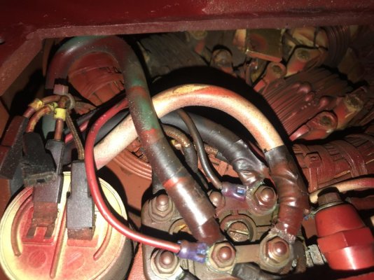
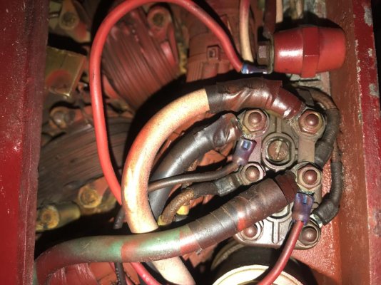
Do you have the manual for the generator? It gives steps to diagnose low/no output. It also has wiring diagrams that show what all that stuff is. On quick inspection, I'd guess those wires were added for an external voltage meter. They appear to have non-factory crimped connectors where they attach inside the unit, and appear to be connected to the main AC output terminals. But I can't be sure without knowing your exact model number which looking back through this thread, you never determined.


One thing I see in the schematics is a switch - looks like a toggle switch - that selects between voltage regulation using the transformer, and regulation using an electronic AVR (Automatic Voltage Regulator). If you have no AVR and that switch is set to "ELEC", then I think you will get no output. Check to be sure it's set to "COMP" to use the transformer.
 
Yes you were right about the black small one goes to the L1 or AC black lead so 110 volts AC and the Red small wire is connected to green or AC ground wire and comes out and has a fuse on it and they both just go to a small little white connector not on anything. The red wire in the picture that i'm thinking supposed to go to my dc 12 volt positive wire to get 12 volts DC, because I think it was connected that way, but I'm not sure. goes in there and is connected to that red isolator on the top but I'm not sure about that and don't want to connect it until I'm sure of it.:banghead:
 
What else is connected to that red isolater thing? I can't tell what that is or what it's for.


Any sign of the switch to select between "COMP" and "ELEC" for voltage regulation?
 
No there’s no switch anywhere like that.
 
This red wire I’m talking about because I think it was connected to my 12 volt dc positive and no it does have other wires connected to it but they go inside where I can’t see.
 

Attachments

  • A7BCD56B-6E4F-48DE-841B-4BA7BE33F505.jpg
    A7BCD56B-6E4F-48DE-841B-4BA7BE33F505.jpg
    157.7 KB · Views: 38
  • 99EBF3F1-58FA-45F2-B73B-2AA0877043E0.jpg
    99EBF3F1-58FA-45F2-B73B-2AA0877043E0.jpg
    95 KB · Views: 36
The red thing isolator is hanging down from the top of the case. Don’t know why the picture is now sideways.
 
I would forget about the red wire, and focus on working through the steps in the manual to figure out why the generator isn't producing output.
 
Looks like a capacitor regulated unit, can see what looks like a capacitor in some of the pics. Test or replace the capacitor. Some higher end multi-meters have a microfarad setting that will test a capacitor. Otherwise, follow the manual. Looks like the L0, L1 and GND are hooked up as normal.
 
OK. So don't hook up the wire to 12 volt positive? I'm going to ground it to my main engine today too and try cleaning up the wire ends.
 
OK. So don't hook up the wire to 12 volt positive? I'm going to ground it to my main engine today too and try cleaning up the wire ends.

Suggest you follow Ski's advice in his previous post. He is a rock solid source for all things genset related, as well as other knowledge.

You run the risk of creating issues where none exist.
 
Just cleaned it up and of course used my fluid spray on it to make everything new looking again and working like a charm and running my AC and Air Conditioner and that's all I need. Noisey though and would like to rig and rpms just to see if it's at 1800. I'm thinking that's what the manual calls for. Seems to me it running faster and pumping a lot of water out the back.Thanks guys mission accomplished . :whistling:
 
Yes. Taped and zipped tied them wires up. Must not need them.
 
What did you fix to get it to start making power? Or did it just do it on its own?
 
Just cleaning it up I guess. Who knows.
 
I took all the wire clips off and sanded them too. So maybe just better connected. Fluid spay made them look brand new. I can post another picture. Looking good now.
 
Hey back to the generator!!! Was not worrying about it but thought I might ask. My electrical system plugged into my dock has 118 volts. Yes suppose to be 110v but by this gauge it says 118.0 volts and my generator is putting out 153.0 volts. Is it going to burn something up? I know you have to change the RPMs to make it come down and have no clue how to change the generator governor and was wondering what rpms that It's actually running and haven't compared it to another one but thinking it seems high.
 
Do you have any kind of manual?


Shore power is usually up near 120V.
 
manuals online

Westerbeke has them on their site.

158v is a problem

Here is a troubleshooting guide that may help

https://www.westerbeke.com/troubleshooting%20guide/bc_troubleshooting_manual.pdf
 
Back
Top Bottom