Air Leak from Fuel Tank?

The friendliest place on the web for anyone who enjoys boating.
If you have answers, please help by responding to the unanswered posts.
Really? Naah...you're pulling our legs.

I have built boats with twin saddle tanks, single engine, no cross over. After the boat is built the supply and return valves are adjusted until tanks are drawn from and returned to evenly, after which the handles are removed and wire tied adjacent to the valve. It can be made to work properly....

Re: "I have built boats with twin saddle tanks, single engine, no cross over. After the boat is built the supply and return valves are adjusted until tanks are drawn from and returned to evenly, after which the handles are removed and wire tied adjacent to the valve. It can be made to work properly."

No, it can't. But you're kidding right? I hope you are because I want to laugh here and say "O.K. Steve, you had me going..."

This would be a total kludge, and (if you think about what you just said) it is readily apparent that this kludge can only work if the tanks somehow, miraculously remain at the exact same fill level over the years, and the engine is always run at it's max fuel flow rate. Never going to happen.

1) In this design, where does the generator draw from/return to? Do you propose the same kludge for that?

2) In this design, when you need to shut off the fuel valves (functional fuel shutoff valves ARE required by ABYC) -- how do you do that when you have "removed the handles and wire tied them".?

3) Re: "the supply and return valves are adjusted until tanks are drawn from and returned to evenly". Really? Using what measurement tool or method? Using "flow restriction" to balance fuel draw, you'd need to adjust them while pulling the maximum gph draw from the engine, but then, when running slowly at let's say, 1/10th the gph of maximum draw, the whole system would become useless and revert to a simple gravity feed. The restriction presented by any orfice varies exponentially with flow rate. At lower flow rates your valve restrictions will do nothing.

4) On the return side, you are seriously going to place restriction valves in the fuel return lines and adjust them to "balance the flow" among the tanks? What fuel flow rate do you use for this? You do know that (once again) whatever restriction you choose will only work for the specific flow rate you've chosen, right? And of course, if you mess that up (even a little) you are going to destroy an injector pump and/or blow up the return fuel lines and spray fuel all over the bilge. Check with any diesel engine manufacturer on that, and I am pretty sure ABYC won't let you do that either. Incredibly dangerous.

Good one Steve...you had me going.
 
Wow...

re: "Bungs are there, at bottom and just a few inches from the front. Looks like they were welded in the tank but never connected."
So here is the latest chapter, not resolved yet but I think the problem has been identifed.
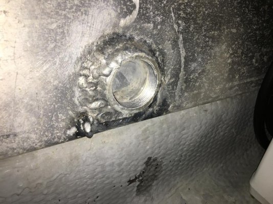
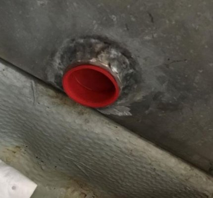
First picture is of the crossover bung which has never been connected.


That red cap stuffed into the bottom of your tank where the crossover hose was -- looks like plastic. NO WAY that was done by a professional.


Someone has REALLY kludged up this boat.


At this point, I am guessing someone tried to "fix" the leaky fuel pickup tube by "retiring" the entire tank, and in the process they removed the crossover hose and crammed a plastic cap into the hole(s).


Unbelievable...but good job getting (almost) to the bottom of it.
 

Attachments

  • !!bunghole.JPG
    !!bunghole.JPG
    39.2 KB · Views: 33
Don’t forget that if both feed valves are open, and there is no air in the piping the top feed lines from both tanks are in fact a “crossover”, and will equalize the tanks as a siphon just as surely as a bottom connected crossover....


Good point...I stand corrected. That said, what do you think of this?


That red plastic plug is at the very bottom, foreward corner of the tank.


I (for one) would not put fuel in that tank.
 

Attachments

  • !!bunghole.JPG
    !!bunghole.JPG
    39.2 KB · Views: 36
I too am going to disagree on this. I have a single diesel with saddle tanks, and valves for both supply and return. No dedicated cross connection. I always return to the same tank as I draw from, and manage athwartship trim by drawing from the appropriate tank, switching back and forth to draw them down somewhat evenly. Usually I switch every couple of days. I also have water tanks P&S, and so if one is full and the other empty I can maintain trim by running one fuel tank at a higher level to offset the imbalance. This system has worked well for me.

If the fuel return goes to only one tank then a cross connection is needed, but that seems to me to be a short cut solution.


Yes...so rethinking this I am wondering why the MS350/390's made the crossover hose standard on the singles?


The siphon action of the cross-connected pickup tubes could keep tank levels balanced (albeit slowly), but is the generator a factor? Could it have been a safety thing for the inevitable times when owners forgot what position they'd left the fuel valves in? Or, is it just so owners don't (necessarily) have to fill from both sides and then wait a few days for tanlk to balance out via the pockup tube hoses?
 
This thread reminds me of one on my “pet peeves” from my days in industrial maintenance. Electricians were the worst, and since no electricity is involved in this thread I’ll stick with them to minimize offending all the contributors of good ideas in this thread.
Something quits working, and the electrician is called. He does his troubleshooting and decrees that “it is wired completely wrong, no wonder it doesn’t work”. Boss tearing hair out “it has worked for 20 years this way, something changed that made it stop working. Go find what changed”.
I fall into the trap all the time. Fixing things most often requires finding what changed, and I go off critiquing and looking for improvements in the whole system. The latter is a worthwhile endeavor, but if the goal is to restore yesterday’s operating condition, it sometimes delays me finding “what changed”, and getting going again.


Hey...I might resemble that remark! ;-)


As owner of a MS390, I know that crossover is supposed to be there in the first place, and now seeing that red plastic cap stuffed into the hole where it used to be is a danger sign. I agree that discovering how it was built in the first place, and then finding out what's been changed usually is the quickest way to find the problem.
 
Yes...so rethinking this I am wondering why the MS350/390's made the crossover hose standard on the singles?

My assumption has always been that it was cheaper to plumb a single return and crossover than to have switchable returns. Maybe too they wanted to keep things simple for owners.
 
HI, On the old Celestial, (now destroyed by Hurricane Michael), I ended up replacing all of the valves as a result of installing a fuel polisher. The problem was that I used garden variety valves, I found that most valves are rated for pressure only, not for vacuum. I finally had a long conversation with the Conbraco valve technicians. They confirmed that their Apollo valves were rated for both pressure and vacuum (at the time, their catalogs did not state the ratings). I replaced all of the valves in the entire system with Conbraco's Apollo valves and the problem of air infiltration almost stopped. I also found that the Racor 1000's have a tendency to leak (vacuum) in several places, which I tracked down one by one and eliminated. In the end, the fuel system was very tight, i.e., no fuel leaks under any circumstances.
 
Crossovers are not needed in many cases.

You can run on and return to one tank at a time.

Plenty of boats set up this way.

The only boats II have run (that I recalll) with crossovers were so you could fuel just one side. Had nothing to do with the engine (s).
 
Last edited:
Crossovers are not needed in many cases.

You can run on and return to one tank at a time.

Plenty of boats set up this way.

The only boats II have run (that I recalll) with crossovers were so you could fuel just one side. Had nothing to do with the engine (s).

:thumb:

And I simply do not see the rationale for ever drawing and returning to two tanks at the same time.
 
Good point...I stand corrected. That said, what do you think of this?


That red plastic plug is at the very bottom, foreward corner of the tank.


I (for one) would not put fuel in that tank.


Well, I didn’t think about it until you asked, because it does not seem to be leaking. Now that you ask, here’s my guess. We know that we have a very thoughtful tank builder, based on their ability to supply drawings of a tank made 20 years ago, and having a ready to ship dip tube to fix a weakness in the original design. My guess is that as a convenience to the future owner they welded on a weldolet to ease the future addition of a drain plug, or bottom discharge without having to weld on a tank in place, or with fuel residue, but they did not drill the hole in the tank plating. That red plastic piece is not even threaded, it is simply a dust plug to keep the female threads clean as we wait for someone to need or want to drill the hole.
 
Just my 2 pence, its highly unlikely that there are pinholes in the lift tube but never assume anything because that makes an ass out of u and me. Anyone who buys a s/h boat will tell you PO's are everybody's recurring nightmare.
I would not assume the Racor to be perfect. One test option is to pressurize your feed line with air (liquid can form a seal) brush all joints with soapy water, check for leaks.
Be methodical and patient and you'll master it, if a man made it then a man can fix it, please let us all know the outcome so we can all learn from your experience.

I had a similar very embarrassing nightmare once when I fitted a CAT filter/water separator, at one connection I'd enthusiastically overtightened it and distorted the end of the pipe, it didn't show a leak, when the engine was running it drew in tiny amounts of air which eventually built up and every time I was passing through a lock it stopped the engine.
 
1) In this design, where does the generator draw from/return to? Do you propose the same kludge for that?

2) In this design, when you need to shut off the fuel valves (functional fuel shutoff valves ARE required by ABYC) -- how do you do that when you have "removed the handles and wire tied them".?

3) Re: "the supply and return valves are adjusted until tanks are drawn from and returned to evenly". Really? Using what measurement tool or method? Using "flow restriction" to balance fuel draw, you'd need to adjust them while pulling the maximum gph draw from the engine, but then, when running slowly at let's say, 1/10th the gph of maximum draw, the whole system would become useless and revert to a simple gravity feed. The restriction presented by any orfice varies exponentially with flow rate. At lower flow rates your valve restrictions will do nothing.

4) On the return side, you are seriously going to place restriction valves in the fuel return lines and adjust them to "balance the flow" among the tanks? What fuel flow rate do you use for this? You do know that (once again) whatever restriction you choose will only work for the specific flow rate you've chosen, right? And of course, if you mess that up (even a little) you are going to destroy an injector pump and/or blow up the return fuel lines and spray fuel all over the bilge. Check with any diesel engine manufacturer on that, and I am pretty sure ABYC won't let you do that either. Incredibly dangerous.

Good one Steve...you had me going.
There at least five vessels (maybe more, I've lost count) that I'm responsible for, cruising happily with this set up, some more than 20 years old.

1. Genset draws and returns from/to either tank using valve manifold (and so can the engine btw, so you could run the engine on one tank if necessary).
2. ABYC guidelines don't specify the speed with which this must be done. Actuating these valves is primarily in the event of service or fuel system repair. Some owners chose to reinstall the handles and leave them that way, that was their choice. Fuel filter replacement is easily accomplished by turning off the Racor tandem filter valve. One owner requested that the supply valves be operable from the cabin, we installed remote cables and left the handles in place. After some high profile engine damage, it's now not uncommon for boat builders to remove return valve handles.
3. Never the less, it was done and it worked, for thousands of engine hours. In practice self leveling occurred at rest via the drop return tubes (all the tanks have drop tubes for returns to prevent aeration and air ingestion via a return line, it's a requirement from some engine manufacturers).
4. There is no ABYC guideline regarding this detail. In practice the necessary restriction on the return line was minimal, no more than 20 deg. of valve closure if I recall, and while I agree a closed fuel return valve can cause damage, in this case there was no risk of "blowing up" a fuel injection pump because of the minimal closure. You'd have to mess it up a lot, i.e. closing the valve most or all the way. If a siphon can occur, supplying a leak, the valves themselves are mandatory for ABYC compliance.
 
Well, I didn’t think about it until you asked, because it does not seem to be leaking. Now that you ask, here’s my guess. We know that we have a very thoughtful tank builder, based on their ability to supply drawings of a tank made 20 years ago, and having a ready to ship dip tube to fix a weakness in the original design. My guess is that as a convenience to the future owner they welded on a weldolet to ease the future addition of a drain plug, or bottom discharge without having to weld on a tank in place, or with fuel residue, but they did not drill the hole in the tank plating. That red plastic piece is not even threaded, it is simply a dust plug to keep the female threads clean as we wait for someone to need or want to drill the hole.

Island Cessna has nailed the red plug's existence. Those red plugs always(in my experience) accompany any item that has an open port into which a hydraulic hose/fuel hose etc is to be plumbed. They were never designed to be a stopper, only a dust prevention device.
If that one is being used as a stopper, it is not adequate for that job and should be replace with a proper stopper or a valve, as it WILL fail as a stopper, just a matter of time.
 
So I originally started this post to ask about info on the pick up tube removal or how to fix an air leak. I didn’t know it was going to turn into a debate about fuel line design and who F-up the system. I believe this setup is original and it has worked for 21 years. I didn’t realize how opinionated some responses would be. For all the helpful responses I thank you. For others, not so much.

Here is the picture of the bung with plastic cap removed, no hole in the tank. If anyone thought that the plastic cover was the only thing that was holding back 150 gallons of diesel fuel then I guess you should re-think your responses. It looks like the bung was welded and the tank was never cut into. Nice that it is there in case you want to add a drain or cross over. BTW, went on a sister boat, a 1999 350 and it is the same way. So I guess it was the way the factory did things back then. I don’t believe process control was big with Mainship in the 90’s like it is today with new automated manufacturing.

Still waiting the delivery of the replacement pick up tube, will keep you posted on outcome. Thanks.
 

Attachments

  • 8824FB0F-ABCF-4134-A979-573B5618FD61.jpg
    8824FB0F-ABCF-4134-A979-573B5618FD61.jpg
    168.6 KB · Views: 28
Potentially a bottom site gauge mount, maybe. I wouldn't fly with that weld job though...
 
Rereading your original post and a lot of the following.

You say there is a valve atop the tank that the fuel line then runs to the Racor.
When the valve is open bubbles show, when the valve is closed no bubbles, correct?

Maybe the valve itself is the problem. Even ball valves have a stem seal usually with an adjustment nut. Take a look at the stem for a nut where the stem enters the ball valve body. Try tightening the nut. The seal can and does wear and vacuum can pull air in where fuel will not leak out. The handle should take a bit of force to turn. If it turns too easily then the seal may not be working as expected. Of course some of the force is needed to turn the ball in its seals but take a look and try the nut.

There was someone else recently who had a similar air entry problem and it turned out to be his valves. They were gate valves but the stem seals simply needed to be adjusted. If no joy then replace the valve with a GOOD one. Some new B.V. , although attractively cheap , have no place in a fuel system.
 
References...

Still new to me, 98 Mainship Trawler with single 370 Yanmar, 2 157 gallon tanks. A couple of months ago my engine stopped leaving me stranded. ...Help, I’m tied of of smelling diesel fuel.

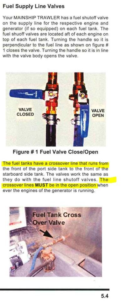
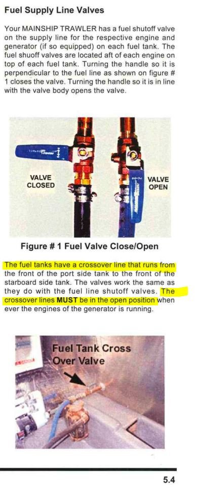
Image #1: From your owner's manual. The fuel system on your boat was designed to have a crossover hose. If it does not, I'd bet money it's either a factory oversight or a subsequent owner has removed it. I can tell you that welding around your fitting does not look like the factory welds on our 2003 MS390 tanks.

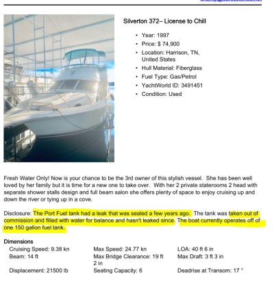
Image #2: Luhrs also built Mainships and Silvertons. Here's an example of a 1997 Luhr's built boat with a leaking tank that was 'kludged' by disconnecting it and filling it with water (see listing on yachtworld). Perhaps Luhrs/Mainship/Silverton were having fuel tank supplier problems during these years? I think others have suggested this.

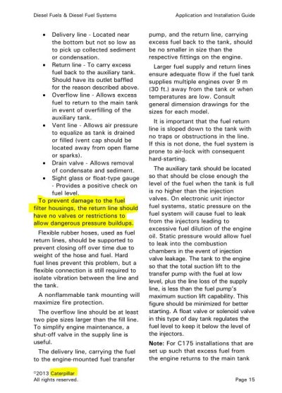
Image #3,#4: Quick reminder from people who know as to why you should never have any shut-off valves, 'proportioning' valves, or any other restrictions in your fuel return lines. The only fool-proof way to ensure you don't overflow a tank with the output of your return lines is with a crossover hose.

I sure didn't mean to upset you with comments about your boat and what was messed up at the factory or by a previous owner. I've found things like this on pretty much every boat I ever owned.

In my experience, the vast majority of manufacturing defects never get fixed because previous owners didn't think to look, or if they did look, didn't know enough to question things that aren't right.

After nearly 40 years of this, I have seen the most amazingly stupid things happen in manufacturing, even to some of the best-designed boats. -- it would not surprise me at all if the factory clods simply 'forgot' to install that crossover, on your boat and perhaps others. It might have been going on for months or years.

Back to your pickup tube...if I were you, after you fix this I would start thinking about "why did my fuel pickup tube corrode and fail and leak"? The aluminum inside a 20-year-old diesel tank doesn't just start corroding to the point of perforation without an underlying root cause. Maybe a bad weld. Ok, that's understandable. But if it didn't fail at the weld, I think you want to know why it DID fail. Is the pickup tube on your other tank ready to fail too?

Microbial infestations of diesel fuel tanks produce extremely corrosive waste products. I would definitely cut that hole in the floor above the tank, remove your fuel sender and get inside there with an endoscope and look around. We did this to our MS390 right after we bought it and had the tanks cleaned. Really nice to be able to pop the tank sender and look around in there.

Again...didn't mean to disparage your boat or it's previous owners.
 

Attachments

  • crossover.JPG
    crossover.JPG
    81 KB · Views: 21
  • Luhrs.JPG
    Luhrs.JPG
    85.6 KB · Views: 30
  • CAT_Return_Lines.JPG
    CAT_Return_Lines.JPG
    124.5 KB · Views: 20
  • SBMAR_Return_Lines.JPG
    SBMAR_Return_Lines.JPG
    47.7 KB · Views: 20
Potentially a bottom site gauge mount, maybe. I wouldn't fly with that weld job though...


Agreed (about the weld job). Looks like 'field work'. I don't think that was done in any factory.

Re: "Potentially a bottom site gauge mount, maybe."

Nope...see photo. These boats were designed with a crossover hose there...
 

Attachments

  • crossover.JPG
    crossover.JPG
    81 KB · Views: 26
...Anyone who buys a s/h boat will tell you PO's are everybody's recurring nightmare....
...


You said it man.


In my experience, better than 90% of what's broken or effed up on any boat is either undiscovered factory defects or a previous owner's mistakes.


By this I don't just mean PO's DIY jobs...at least half of the so-called 'professionals' out there are incompetent...
 
My assumption has always been that it was cheaper to plumb a single return and crossover than to have switchable returns. Maybe too they wanted to keep things simple for owners.

Re: "My assumption has always been that it was cheaper to plumb a single return and crossover than to have switchable returns."

The UL approved crossover hose and it's ABYC and UL approved fittings costs about 50x more than the cost of "switchable returns". I know this because the surveyor who did the pre-purchase on our MS390 flagged the crossover hose and made the seller replace it because he could not find the proper certification markings on the hose. Sadly, after the mechanic got the old hose/fittings out, sure enough there were the certification markings.

Re: "switchable returns" -- The problem here is that if someone ever screws up the return valves and somehow leaves them both in the 'closed' position, you can destroy (or very severely damage) your engine. AFAIK, all diesel engine manufacturers are unanimous on this -- there must be no valves or restrictions in the return lines.
 
https://www.powerandmotoryacht.com/electronics/parker-fuel-tank-selector-valve


Yet another big-time industrial manufacturer reaches up into the electronic helm. Parker’s Fluid Control Division developed this solenoid drive selector valve so that a skipper can change tanks without leaving the helm. In fact, the first customer, Hinckley, set it up to switch tanks automatically based on fuel levels. That six-port model you see is able to handle the supply and return lines for two tanks and a single diesel. Almost any configuration is possible, and all include fail-safe manual overrides and thus are rated as safety shut-offs. Prices available on request.
 
Last edited:
Re:

Re: "switchable returns" -- The problem here is that if someone ever screws up the return valves and somehow leaves them both in the 'closed' position, you can destroy (or very severely damage) your engine. AFAIK, all diesel engine manufacturers are unanimous on this -- there must be no valves or restrictions in the return lines.

Many boats in commercial survey require shut off valves in both lines for fire safety.
They have a connector rod between both valves though so that one cannot be opened or closed without the other so that no one can screw up.
 

Latest posts

Back
Top Bottom