Perkins gen. shuts down after 10 min.

The friendliest place on the web for anyone who enjoys boating.
If you have answers, please help by responding to the unanswered posts.
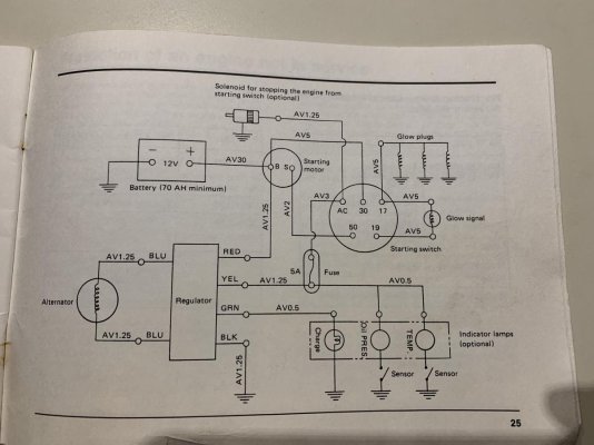
This does not make sense to me. The solenoid is either power to run or power to shutdown. Since you now have to shut it down with a stick says power to shutdown. But if that was true and the solenoid power was bad, the engine would run forever.

Unless a sensor was going bad and telling the solenoid to shut the engine down. Or worse, an actual bad engine condition causing the engine to shutdown. So what your mechanic did was effectively bypass all of the protective trips. Ok for troubleshooting but a disaster waiting to happen if something bad exists.

:confused:So while the engine was running:
Adequate water flow out of the exhaust?
Coolant temp normal on gauge?
Exhaust riser temp <200F?
Normal oil pressure on gauge?

I am confused, too. The mechanic had limited time, so he could not continue. I was not on the boat, so I don't know the answers to your questions. I'll be there tonight and I can run it, but I don't want something bad to happen. If I do run it for a short time, I could look up the results.

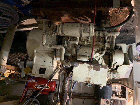
The mechanic said that there is no power to the solenoid whatsoever. The solenoid was functioning fine removed and connected to a battery directly, but not on the gen. It does not get power.
 
It least you ruled out fuel and injector problems. I would have hoped that the mechanic checked those parameters while the engine was running but you can't assume he did.
Do you have a manual and does it have a wiring diagram? Posting a copy of the diagram here would help.
 
I’m watching this closely. I have generator issues right now going on.Mine is shutting down after about three minutes. It will start right back up and then shut down in 2 to 3 minutes. The solenoid is staying locked in but still the engine is shutting down. I put a new solenoid on a couple years ago. I’m changing all fuel filters this weekend and ruling out fuel problems. I replaced my exhaust water temperature sensor last year when I installed new exhaust elbow. It ran six straight hours the day before it started this then the next morning it started acting up.
 
Marty, you say the solenoid stays locked down while the engine stops? If that is so, it sounds as if there is something wrong with the control circuit because one would think the solenoid would open when the engine sputters to a stop.

I had an Onan with a centrifugal switch, and oil pressure switch and a heat sensor switch in series with each other, and any one of the three could make the unit shutdown which caused the solenoid to close the fuel line. The way I troubleshot them was to bypass each of them one at a time by connecting a test wire around them to see if the engine would run without it in the circuit.

Otherwise it is a fuel supply issue which shuts the engine down which in turn shut off the hold-open current to the solenoid stopping the engine.
No it stays locked in until engine completely quits then it opens.
 
Oh, ok, my misunderstanding. What you describe is what I would consider normal for a control/protection circuit induced shut-off. Can you access the switches which shut your unit down and wire around them temporarily to test each one?
 
...We have checked the batteries several times. The voltage was normal 12.4V
They are also charged from shore power, as it is now.
Probably irrelevant to the issue, but 12.4V batts is not normal. Voltage is not a perfect test but "full" is 12.6V or above.
 
Do you have a manual and does it have a wiring diagram? Posting a copy of the diagram here would help.


I took some photos last night.
The mechanic said he had run it for 45 minutes and did not see a problem.
 

Attachments

  • S5tl8vJyRqGNPJOZ1GIfyQ.jpg
    S5tl8vJyRqGNPJOZ1GIfyQ.jpg
    151.3 KB · Views: 41
  • ZBrl7uEdQGm3R51hK3C0OA.jpg
    ZBrl7uEdQGm3R51hK3C0OA.jpg
    196.6 KB · Views: 41
  • 80Klg7C%RJumIQi2Wk5U+Q.jpg
    80Klg7C%RJumIQi2Wk5U+Q.jpg
    189.6 KB · Views: 31
  • LkDMofuzS5219lHviQoq+w.jpg
    LkDMofuzS5219lHviQoq+w.jpg
    141.4 KB · Views: 41
  • rQK5Jxf1TxSpqm%JnqCqkw.jpg
    rQK5Jxf1TxSpqm%JnqCqkw.jpg
    102.1 KB · Views: 46
  • tN0NWLVgQpaxf1UpgyAelw.jpg
    tN0NWLVgQpaxf1UpgyAelw.jpg
    103.7 KB · Views: 36
Probably irrelevant to the issue, but 12.4V batts is not normal. Voltage is not a perfect test but "full" is 12.6V or above.


I will check it again today. The 12.4V was after sitting on anchor for an hour or more and the the main engine would not start. So, we checked the voltage. The problem was something with the Matthew control system, not the batter.
 
find and check the 5 amp fuse shown in the last picture. It may be hiding in the gray control terminal box.
 
Last edited:
find and check the 5 amp fuse shown in the last picture. It may be hiding in the gray control terminal box.

Well, I tried last night. I just could not.
The solenoid has one wire connected to it with a number '3' on it. I followed the wire to the gauge box, but all I can see that it comes in on connection rail third position, goes around and ends at the ECU-PMT1 box connection number five. You can see it on the photos I attach. I removed the ECU box, but it is sealed. There is nothing I can see inside of it. The gauges are getting power from the same source just fine. If that 5A fuse is in there, I need to buy a new box. It does not make sense to have the fuse there, but I cannot see it anywhere else on the engine.
Let me know what do you think?
 

Attachments

  • JQ+laNm%TQKCguCOndFRsg.jpg
    JQ+laNm%TQKCguCOndFRsg.jpg
    184.7 KB · Views: 54
  • V1nKE1eeQlOl56tmub1Gdg.jpg
    V1nKE1eeQlOl56tmub1Gdg.jpg
    164.1 KB · Views: 40
  • vv%KZ%OfSumd+4vK4jxosQ.jpg
    vv%KZ%OfSumd+4vK4jxosQ.jpg
    178.4 KB · Views: 52
  • lTjCVWRhTsmyK8fj16CqPQ.jpg
    lTjCVWRhTsmyK8fj16CqPQ.jpg
    154 KB · Views: 39
  • 7TlhCvyqSfqLyWasRGuAcQ.jpg
    7TlhCvyqSfqLyWasRGuAcQ.jpg
    153.8 KB · Views: 38
Probably irrelevant to the issue, but 12.4V batts is not normal. Voltage is not a perfect test but "full" is 12.6V or above.

I checked the voltage on the Magnum charger/inverter remote display and is is showing 12.5-12.6V steadily on shore power. The cranking batteries are included in this on shore power. I see 12.5V on the cranking batteries directly.
 
Well, I tried last night. I just could not.
The solenoid has one wire connected to it with a number '3' on it. I followed the wire to the gauge box, but all I can see that it comes in on connection rail third position, goes around and ends at the ECU-PMT1 box connection number five. You can see it on the photos I attach. I removed the ECU box, but it is sealed. There is nothing I can see inside of it. The gauges are getting power from the same source just fine. If that 5A fuse is in there, I need to buy a new box. It does not make sense to have the fuse there, but I cannot see it anywhere else on the engine.
Let me know what do you think?

in the first picture, those 3 white rectangles are fuse holders. pull the fuses one at a time and test each for continuity. I think the top one would be the prime suspect.
I doubt you need a new box.
 
Last edited:
in the first picture, those 3 white rectangles are fuse holders. pull the fuses one at a time and test each for continuity.
I doubt you need a new box.
Yes, the ones that have "pull" on them. They are glass tube fuses beneath.
 
Well, here is some result. I hired a diesel mechanic and he traced it down to the solenoid.
First, the solenoid is not getting power. He traced the wire back to the instrument panel and out of 3 yellow wires, this one does not get any. The two others do. He said that this wire goes to a control unit, so that has to be investigated next time.
He removed the solenoid and the engine runs fine. It ran it for half an hour and there was no shut down. Obviously, it has to be shut down manually now with a stick, since the turn on/off key controls the solenoid.
I know this is strange and might not makes sense, why was it running before, but shutting down after 10 minutes.
Any clue or input will be appreciated.

From post #57:
The yellow wires labeled #3 should all be connected together. Meaning there should be continuity at every end to every other end of #3. If not then the wire is broken somewhere.
With everything powered down, check the continuity between terminal block and that quick connect terminal for the solenoid for wire #3.

Thank you. I will do it this weekend.
I was afraid to pull those, because they looked to big for a fuse. Plus, wire #3 goes around them. It is more clear now. I hope that one of them is bad and I can replace that for success. I'll report back.

I tried to buy the solenoid online, but I cannot locate it anywhere. Some on the eBay are similar, but there is no part number to identify it. I cleaned the paint off it and I could see this number: MV1-17 740. Nothing else. The company on the photos is out of business, so I am not sure where to get solenoid for a Perkins 100 series engine, which was built in 1985? I understand that the solenoid could be just fine, but I always like to have backup of things.

Same applies to the oil pressure sender, which is dead. The gauge is fine, but does not show anything. At the oil/filter change, the mechanic used his own gauge directly on the engine and the oil pressure was fine. It would be nice to know a source, which sells parts for old engines like this.
 
Last edited:
I have opened those switches and found fuses. However, none of them is 5A. They are 35A. I am not sure, if that is correct, or do I need to keep looking?
 
Check them

I'll get insignificant Ohm readings. The relay does not show anything.
The relay is on the top and the two identical 35A fuses are 2nd and 3rd.
Here are the photos.
 

Attachments

  • xFU3LrguQJu61c3KfpI07A.jpg
    xFU3LrguQJu61c3KfpI07A.jpg
    130.9 KB · Views: 35
  • ZAwoBuyLQd2f6OtFERcykg.jpg
    ZAwoBuyLQd2f6OtFERcykg.jpg
    139.7 KB · Views: 30
Last edited:
On those fuses you won't really get an ohms reading other than almost zero. You will get either zero ohms or overload.
-Zero or close is good. CLose is a few ohms like a couple since your probes sometimes can cause that.
-Overload or very high ohms means a blown fuse.


As for the oil pressure sw. you do not/should not need that specific part number. Lots of similar switches around. THere may be a pressure stamped or marked on the body by pulling it. Just find a similar unit at a good auto parts store, chandlery or a truck repair/parts place.

I will say the same for the relay. Try googling that ,mfgr name and p/n and you might find the ratings for it and then look at other mfgrs. as there almost positively will be another , just from a different mfgr. Or contact a generator repair place telling them what you have including a photo if need be. Have the gen model , serial and mfgr name handy as they may/most likely will a have a substitute.
 
Last edited:
I wonder why the electric schema is showing a 5A fuse and I see these fuses to be all 35A? All these 3 fuses check out for connectivity. However, I can only measure 1.2-3V at the end, when I turn on the key. Can the schema be to a different model? Where is the 5A fuse?
The 3 fuses I found are listed under the AC regulator unit. The 5A fuse is shown between the solenoid and the AC regulator unit, on every schema I have. I just can't see it.
 
They are NOT 35 amp fuses! One of them is 1 amp, one is a 30 amp and the middle one I cant read. The amp value is stamped into the endcap. ie 30A is a 30 amp fuse.
What does "insignificant ohms" mean? Less than 1? infinity?

What relay?
Seriously you need to get a marine electrician on board.
Your diagrams do not seem to match your generator.
 
Last edited:
They are NOT 35 amp fuses! One of them is 1 amp, one is a 30 amp and the middle one I cant read. The amp value is stamped into the endcap. ie 30A is a 30 amp fuse.
What does "insignificant ohms" mean? Less than 1? infinity?

What relay?
Seriously you need to get a marine electrician on board.
Your diagrams do not seem to match your generator.

The first one, the 30A says on it ' relay '. The two other green ones are the same. Let's say they are 1A each. It is still confusing, because the drawings never show 1A fuse anywhere.

Yes, I am not an electrician. At this point, the boat is on anchor/off grid. It would extremely difficult for me to drag anyone to the boat in a tiny dinghy. Maybe some day. Till then, I am trying to do what I can to solve this issue.
I have purchased a portable generator and I am running it from propane. At least, I can have electricity, when I need it. It is not as noisy as the Perkins.

Maybe it is time to see, what the real schema is for this Perkins? The original bill with details includes 4 different schemas. The single schema, which lists the 5A fuse for the solenoid is from the standard manual, so it might not be appropriate.
I need to keep researching this.
 
Check for dc power on terminals 2&3 on the ecu pmt1. if you have dc power. jump terminal 4 to terminal 5 and see if the fuel solenoid picks up.


PMTN Home
 
Check for dc power on terminals 2&3 on the ecu pmt1. if you have dc power. jump terminal 4 to terminal 5 and see if the fuel solenoid picks up.
PMTN Home


Thanks. I'll do it tonight.
If the solenoid comes alive, what is next? Do I need a new PMTN ?
 
Thanks. I'll do it tonight.
If the solenoid comes alive, what is next? Do I need a new PMTN ?


the pmtn can be configured a bunch of different ways but as best i can tell it looks like its set to a 36 sec on delay. we call it a fault protection timer. it allows the gen to come up to speed and oil psi/water temp to stabilize before arming. more than likely if you get it to run the timer will be bad. if you fallow the link i posted you can download the manual for the pmtn.


if you do find it bad. you can get a new one from the link below. Ive used with them for over 10 years and never had a single issue.

Your Web Browser does not allow this website to use cookies
 
Check for dc power on terminals 2&3 on the ecu pmt1. if you have dc power. jump terminal 4 to terminal 5 and see if the fuel solenoid picks up.PMTN Home


I think you have nailed it. I followed your instructions and it worked. There was DC power on #2/3. I jumped #4/5 and the solenoid received proper voltage.
With the jumper cable on, I was able to start the Perkins. It ran for a while, until the jump wire fell off. I used only a croc. clip to jump it. The vibration must have moved it.
Unfortunately, at the next step, I blew the 30A fuse, so it is no go for now. Since, I hard wired it the second time, when turned the key on to start, it blew the fuse. I am not sure, why it did not blow it at the first time?
Either way, I am going to buy new fuses today and I will also order a new PMTN.
Thank you for your help and I'd like to know your opinion, why the fuse blew only at the second time? I want to prevent this from happening again.
 

Attachments

  • etO8litORCeMHp9aRUnS1Q.jpg
    etO8litORCeMHp9aRUnS1Q.jpg
    155.1 KB · Views: 28
  • bk9+3RNxQ7Kcsn6FSU+WMg.jpg
    bk9+3RNxQ7Kcsn6FSU+WMg.jpg
    150.6 KB · Views: 26
  • TUMr%WP%Ri6Pq6Vm8TJIvA.jpg
    TUMr%WP%Ri6Pq6Vm8TJIvA.jpg
    198.8 KB · Views: 26
  • J5MOu6sZQV+L8p0UdDvX0g.jpg
    J5MOu6sZQV+L8p0UdDvX0g.jpg
    190 KB · Views: 20
going by the print. its the an l1 ac power fuse. its possible your jump momentarily touched it and popped it.
 
going by the print. its the an l1 ac power fuse. its possible your jump momentarily touched it and popped it.

New unit on its way for around $130 with shipping. It is called ECU-PMT2 now.
I'll stock up on fuses today.
 
New unit on its way for around $130 with shipping. It is called ECU-PMT2 now.
I'll stock up on fuses today.

Make sure to download the manual for and double check the connections and dip switch settings. You definitely want to make sure you have at least two spares for every fuse on the boat. I use the clear water tight Plano tackle box's on my service truck. They do a good job especially considering how much abuse they get.
 
Back
Top Bottom