Convert to 8V Serp Belt

The friendliest place on the web for anyone who enjoys boating.
If you have answers, please help by responding to the unanswered posts.

Wil

Senior Member
Joined
Jul 8, 2013
Messages
187
Location
US
Vessel Name
Gone Walkabout
Vessel Make
1999 KadeyKrogen 39
Our 1999 Krogen 39 has a Deere 4045 TFM diesel powerplant. Our new large housebank (900Ah) prefers to be charged at ~0.4C. So I need a 250-300A large frame alternator for it. That means converting the existing twin 1/2" V-Belt setup to an 8V serpentine belt setup.

Anybody know a firm that sells Deere twin V-Belt to serp belt conversion kits? Thanks.
 
My 4045 wind engine is equipped with a serpentine belt, and I think 8 ribs, but not 100% certain. A good Deere dealer should be able to supply the drive pulley and alternator mounting bracket for a larger alternator. You will also probably want to add a tensioning idler. I would give Hatton Marine a call.
 
I also have a 4045 that came with a serpentine belt. Think it would be quite difficult to replace the alternator with a large frame high capacity one as the length and diameter of the alternator could be problematic. If you plan to charge a large house bank ( mine is 900 ah) you will likely want an external 3 stage regulator. If the bank gets down to 70%, you could be charging in bulk stage for an hour or more. This requires a large frame alternator to handle the continuous load and heat. The compact frame high output alternators aren't designed for continuous output above about 70%.

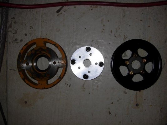
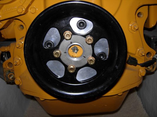
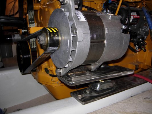
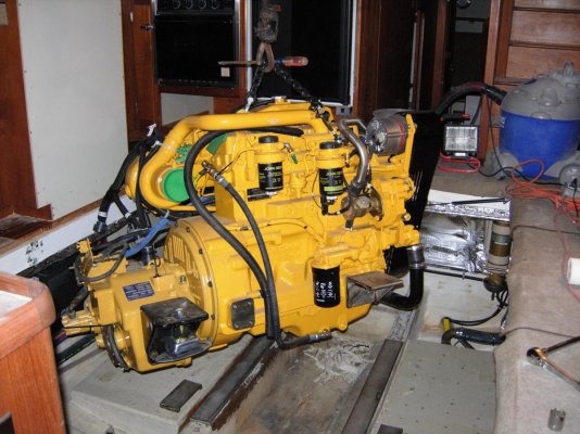
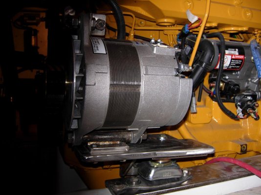
My solution was to mount a second alternator with it's own serpentine belt. Below are some pics of the 2nd pulley & adapter, alternator mounting and external regulator. Pics are during my refit, so the wiring wasn't complete. I like the idea of a second dedicated alternator for the house bank while leaving the original alternator and wiring intact.

DSCN1025.jpg

DSCN1026.jpg

DSCN1027.jpg

DSCN1028.jpg

DSCN1030.jpg

DSCN1038.jpg

DSCN1045.jpg

DSCN1043.jpg

DSCN1047.jpg

3 stage Sterling regulator is mounted on the wall in the upper right corner.

DSCN1033.jpg

Ted
 
Nicely done.
 
Ted, that is a very nice system. Is that all custom made?
 
Ted, that is a very nice system. Is that all custom made?
Yes.

I have a similar setup on my charter boat to power an air conditioner through an inverter. So the design was basically done. The pulley I bought from John Deere. The adapter plate was fabricated by a local machine shop. Since we had to make front motor mounts, I over built them so that an alternator cradle could easily be adapted to them. The rest of the parts were pretty simple and straightforward to make.

Between the alternator, 3 stage regulator, pulley, adapter plate fabrication, and some Sean time, I probably have 1.5 to $2K invested. Tied to my inverter, I have essentially a 3 KW generator run by the generator. With that and a 900 AH battery bank, I've probably eliminated 75% of my generator time.

Ted
 
Ted, really interesting second alternator mounting solution. Nice set of pictures too, thanks. From what I'm seeing, the alternator is mounted on the engine mount, but the belt tensioner is mounted to the engine. Has that caused any issues? It's looking like the serp belt issue is the easier one--mounting a large alternator like that on my relatively small engine will be much harder than I imagined. But forge ahead.

I like the price for that Leece 220A alternator too. I was/am looking at Mark Grasser & Balmar large frame alternators, but they're a pretty big jump in cost.

My Deere is a 1998, back then they did twin V-Belts rather than serp belts. One Deere dealer told me the crankshaft nose shape was changed when serp belts were adopted, so it's not just a pulley change. I do need to confirm if that's true. If it means a crankshaft change to get a serp belt setup, that won't work. Then I'll look into just attaching a second twin v-belt pulley.

The other front in the conversion battle is mounting a large frame alternator as you said. I was thinking I'd adapt my 4045 over to a J180 mount, but that might not be feasible. The externally-regulated (Balmar ARS-5) 12V 115A small frame Balmar on it now only has a 1" foot. And I do like the second alternator idea.

From what I'm understanding of your installation, I'd need to redesign my front left main engine mount to take the alternator cradle, then design up the cradle itself. Do you have a picture showing more detail of the engine mount? Damn, it's easy to get in over my head....
I also have a 4045 that came with a serpentine belt......
…..I like the idea of a second dedicated alternator for the house bank while leaving the original alternator and wiring intact.
…..3 stage Sterling regulator is mounted on the wall in the upper right corner. Ted
 
Last edited:
TT, humourous that my main engine is your wing engine :blush:. I'm in the process of just what you mention, but I'm not sure I can get to a serp belt with how old my engine is. Can you recommend a Deere dealer that is more familiar with Deere marine engines? The ones in my area (farm country north of Seattle) are only familiar with agricultural Deere engines. Hatton Marine is an excellent recommendation, I'll give them a call thanks.

My 4045 wind engine is equipped with a serpentine belt, and I think 8 ribs, but not 100% certain. A good Deere dealer should be able to supply the drive pulley and alternator mounting bracket for a larger alternator. You will also probably want to add a tensioning idler. I would give Hatton Marine a call.
 
Have you looked at the online Deere parts book? It will show all the factory options for alternator mounting. Maybe you can find one that suits your needs. I too would be trying for a j180 mount. Also keep in mind that many pulleys bolt to the pulley that’s on the crank shaft. It looks like that’s how Oc Divers is set up. That might work even if the crank end taper has changed.
 
Ted, really interesting second alternator mounting solution. Nice set of pictures too, thanks. From what I'm seeing, the alternator is mounted on the engine mount, but the belt tensioner is mounted to the engine. Has that caused any issues? It's looking like the serp belt issue is the easier one--mounting a large alternator like that on my relatively small engine will be much harder than I imagined. But forge ahead.

I like the price for that Leece 220A alternator too. I was/am looking at Mark Grasser & Balmar large frame alternators, but they're a pretty big jump in cost.

My Deere is a 1998, back then they did twin V-Belts rather than serp belts. One Deere dealer told me the crankshaft nose shape was changed when serp belts were adopted, so it's not just a pulley change. I do need to confirm if that's true. If it means a crankshaft change to get a serp belt setup, that won't work. Then I'll look into just attaching a second twin v-belt pulley.

The other front in the conversion battle is mounting a large frame alternator as you said. I was thinking I'd adapt my 4045 over to a J180 mount, but that might not be feasible. The externally-regulated (Balmar ARS-5) 12V 115A small frame Balmar on it now only has a 1" foot. And I do like the second alternator idea.

From what I'm understanding of your installation, I'd need to redesign my front left main engine mount to take the alternator cradle, then design up the cradle itself. Do you have a picture showing more detail of the engine mount? Damn, it's easy to get in over my head....

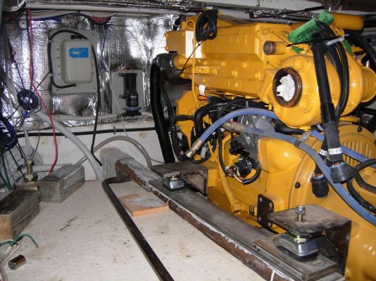
Here are some pictures from the repower that show the motor mount better. They're made of stainless steel and way over built (No kill like over kill :) ).

DSCN0982.jpg

DSCN0986.jpg

No issues with the belt tensioner as the alternator is bolted to the engine.

Deere makes multi groove pulleys designed to bolt to the crank shaft pulley. I just wanted a serpentine belt, so I went the custom route (OCD).

Ted
 
Last edited:
Here is another pic showing the alternator attached to the motor mount.

DSCN1037.jpg

There is a plate welded to the motor mount that has the alternator bracket bolted to it. These plates are so thick that there is absolutely no flexing at all. The alternator is one with the motor!

Ted
 
I am a little puzzled by your 0.4C requirement. That is too high for AGM or FLA batteries and will cause battery overheating and premature failure. Only Li batteries should be charged that fast.


If you drop to the recommended .25C max then two 1/2" belts should be ok at .25*900= 225 amps max. At that much load on two belts, just keep an eye on belt wear and tension. That approach is a lot cheaper than serpentine belts and a new alternator mount.


David
 
Excerpt from the Firefly L15+ manual:

"For repetitive deep cycling, chargers should have an output current of at least 0.4C (40 Amps for a 100 Ah battery). If the output current is less than this value, the cycle life of the battery may be negatively affected."

That caught my attention too.

I am a little puzzled by your 0.4C requirement. That is too high for AGM or FLA batteries and will cause battery overheating and premature failure. Only Li batteries should be charged that fast.
If you drop to the recommended .25C max then two 1/2" belts should be ok at .25*900= 225 amps max. At that much load on two belts, just keep an eye on belt wear and tension. That approach is a lot cheaper than serpentine belts and a new alternator mount.


David
 
Yeh, I've looked at the Deere parts book for repair parts, I'll have a go in the accessories section too. Thanks.

Have you looked at the online Deere parts book? It will show all the factory options for alternator mounting. Maybe you can find one that suits your needs. I too would be trying for a j180 mount. Also keep in mind that many pulleys bolt to the pulley that’s on the crank shaft. It looks like that’s how Oc Divers is set up. That might work even if the crank end taper has changed.
 
Ah, I see. The big thick alternator plate is *welded* to the motor mount--I was wondering if the plate was only bolted to the motor mount by the one big motor mount bolt. How would you change the motor mount if the first one wore out, started sagging? I had to change out the mounts when I bought our boat. Nice pictures too.
Here is another pic showing the alternator attached to the motor mount.

View attachment 79205

There is a plate welded to the motor mount that has the alternator bracket bolted to it. These plates are so thick that there is absolutely no flexing at all. The alternator is one with the motor!

Ted
 
Sorry if I caused some confusion. The cushion part is often referred to as the isolation mount. The bolted on frame between the isolation mount and the engine is often referred to as the motor mount.

In the pictures you can see the isolation mount bolted to the engine bed and bolted to the motor mount. The isolation mounts are easy to adjust and easy to change if necessary as they are held in place with only 2 bolts and 1 nut.

Ted
 
My Deere is a 1998, back then they did twin V-Belts rather than serp belts. One Deere dealer told me the crankshaft nose shape was changed when serp belts were adopted, so it's not just a pulley change. I do need to confirm if that's true. If it means a crankshaft change to get a serp belt setup, that won't work. Then I'll look into just attaching a second twin v-belt pulley.
Be aware that an AX-belt, which is raw-edge and notched, has a higher basic hp rating (before correction factors) than a raw-edge A-belt (which is not notched), by around 20-30% typically. And waaay higher power rating than a 4L (fractional hp) belt (also 1/2" wide), which is usually wrapped (not raw-edge) and not intended for high-speed, high-power applications.
 
Ted & TT; Ok finally got it methinks. My mechanical experience is from the vintage car world where an engine/motor mount is what I understand now to be a (marine) isolation mount. So the thick alternator plate is welded to the engine mounting bracket. Thus that makes the alternator part of the engine, now I see.

Ted, you have the thick plate welded to the engine bracket, and a smaller intermediate alternator mount plate bolted to the thick plate--is that slotted to allow fore-and-aft adjustment, as well as obviously belt tension adjustment?

I'm still looking into the J180 mount possibility, but Ted's setup is sounding more doable now. Remove my left front *engine bracket*, weld a thick (stainless?) plate to it allowing room for the isolation mount bolt, then bolt a (slotted?) intermediate smaller stainless alternator plate--with alternator mount lug (allowing belt tension adjustment) welded to it--to the thick plate. Damn, this is good stuff....:dance:
 
Thanks for the tip. I'll do some research on A vs. AX vs. 4L style belts. I gather from what you're saying the AX belt would be the best one for maximum power transmittal.

Be aware that an AX-belt, which is raw-edge and notched, has a higher basic hp rating (before correction factors) than a raw-edge A-belt (which is not notched), by around 20-30% typically. And waaay higher power rating than a 4L (fractional hp) belt (also 1/2" wide), which is usually wrapped (not raw-edge) and not intended for high-speed, high-power applications.
 
Ted & TT; Ok finally got it methinks. My mechanical experience is from the vintage car world where an engine/motor mount is what I understand now to be a (marine) isolation mount. So the thick alternator plate is welded to the engine mounting bracket. Thus that makes the alternator part of the engine, now I see.

Ted, you have the thick plate welded to the engine bracket, and a smaller intermediate alternator mount plate bolted to the thick plate--is that slotted to allow fore-and-aft adjustment, as well as obviously belt tension adjustment?

I'm still looking into the J180 mount possibility, but Ted's setup is sounding more doable now. Remove my left front *engine bracket*, weld a thick (stainless?) plate to it allowing room for the isolation mount bolt, then bolt a (slotted?) intermediate smaller stainless alternator plate--with alternator mount lug (allowing belt tension adjustment) welded to it--to the thick plate. Damn, this is good stuff....:dance:

There are no slots. I made the alternator bracket by drilling a hole in a piece of round stock and then welding it to the square stainless plate with the 4 holes in it.

I cut a piece of 1/2" plywood to use as a template for the intermediate plate. I clamped the plywood to the motor mount and the alternator bracket to the plywood. Basically I assembled and moved the parts around until I had the intermediate plate size and mounting figured out. Took it all a part, made the intermediate plate, and welded it to the motor mount. Have not drilled the holes in the intermediate plate for the alternator bracket yet. Put the motor mount back on the engine and reassemble the alternator and bracket.

The alignment is very important. Basically you lay a straight edge (4' level) across the face of the crank pulley and the alternator pulley. Once you have the alignment perfect and the alternator bracket firmly clamped to the intermediate plate, remove the alternator, mark, center punch, and drill the holes. When you reassemble everything, the pulley alignment should be perfect. Then it's just a matter of stretching a piece of string around the 2 pulleys and measuring it to figure out the belt size.
The tensioning rod is 1/2" stainless all thread. The bracket on the alternator is a piece of stainless angle iron with 2 holes. Secure the all thread to the angle iron with 2 nuts and lock washers. Then attach the angle iron to the alternator with a bolt and lock washer. All that's left is to fabricate the stainless steel angle iron bracket on the motor. Belt tension adjustment is accomplished by tightening the nut on the thread rod closer to the alternator and then locking it in place with the nut on the other side of the motor bracket. There are lock washers between the motor bracket and each nut.

Ted
 
Ted, thank you for so generously sharing your custom alternator mount info with me.

One final question: how do you work the stainless (weld, drill, cut, trim, file) to fabricate the parts? The welding is probably TIG, so that'll be outsourced. But the parts working? Stainless is an aggravating metal to work...
 
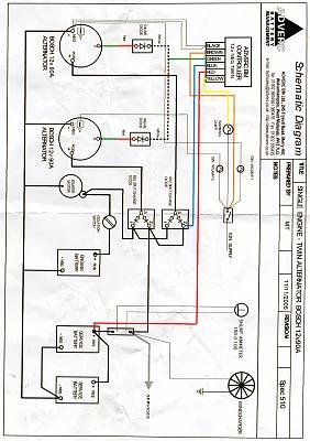
Originally posted by Irish Rambler. Dual alternator wiring diagram.
 

Attachments

  • altrnator.jpg
    altrnator.jpg
    28.4 KB · Views: 182
Ted, thank you for so generously sharing your custom alternator mount info with me.

One final question: how do you work the stainless (weld, drill, cut, trim, file) to fabricate the parts? The welding is probably TIG, so that'll be outsourced. But the parts working? Stainless is an aggravating metal to work...
Stainless isn't tough to work with the right tools.

The boatyard where I did my refit, works primarily on watermen's boats. They use a lot of stainless but the finish generally isn't yacht quality. They stock a suprising amount of flat bar, angle, round stock, etc. The intermediate plate was likely 4" X 1/2" flat bar. You figure out what you need, measure twice, cut and then weigh the piece you want. The yard sells most stainless by the pound, same way they buy it.

Working stainless only requires basic tools. You need a 4" hand held grinder. To cut stainless, a very thin fiber cutting disc on the grinder works very well. It would probably take less than 1 minute to cut off a piece from the 4" X 1/2" stainless flat bar. For rounding corners, dressing the cutoff surfface, and polishing we use sanding discs on the 4" grinder. These discs are specifically for working metal and come in different grits. Usually we have a course one for shaping, medium for dressing, and fine for polishing the surfaces. Don't use sanding discs on stainless that have been used on regular steel. Specks of the steel will remain on the disc, transfer to the stainless, and later form surface rust.

For drilling holes, a drill press is invaluable. The press allows you to apply much more pressure which makes the drill bit cut better. Every hole on that project was done on the drill press. You spend more time bolting and unbolting parts off the engine, but the drilling is much easier.

You need good metal drilling bits (not Harbor Freight junk). Sean has a drill bit cabinet. There are a minimum of probably 10 of every size of the smaller bits (up to 1/2") in the cabinet. There is a bench grinder with a fine stone just for resharpening drill bits. If you want to drill holes in stainless, you need good bits, keep them sharp, use a drill press when possible and use cutting oil to lubricate and cool the drill bit and metal.

While the shop has my MIG and TIG machine including spool guns for stainless and aluminum, most of the welding is done with a simple stick welder. In a commercial yard, they are constantly repairing work boats. Sometimes at the dock, sometimes in the travel lift slings, and sometimes blocked in the yard. A diesel powered stick welder can be moved anywhere in the yard and used in moderate winds. Since that's the only welder that works in all conditions outside the building, it's generally the welder of choice inside as it's what you're use to. If you look at the welds on the alternator bracket, there is no doubt about the quality of the welds you can make with a stick welder and the right rods.

Below is the link to the thread on my refit project. It will give you some insight to the yard I use and the great people who work there. It's a commercial waterman's yard, not pretty, but they have what it takes to do quality durable fabrication.

http://www.trawlerforum.com/forums/s32/my-short-haul-refit-19105.html

Ted
 
Wow, that was one helluva refit project you took on, very well-done sir! I've learned a lot from you, and thank you bunches for it....:thumb::thumb:. Just sold my drill press (selling our home to move onto our KK39), but kept the solid cobalt drill set.

Because my Firefly L15+ 12v/900Ah or 24v/450Ah (leaning towards 24v, but means I'd have to change out the windlass & 4045 starter motor--bow thruster is already 24v) bank needs a 0.4C charge rate for best cycle life, I'm looking into the largest 12v or 24v alternator I can find.

You're the best Ted, thanks again!
If you keep the engine and 1st alternator 12 volt, make the second alternator and house bank 24 volts, I think you'll save some money and it would be a whole lot easier. I thought about 24 volt briefly till I thought of all the things I would have to change. I stopped counting at fourteen 12 volt electric pumps.

Ted
 
That's a good alternative to consider--a 12v-24v system. There are a lot of 12v items on my boat too. I'm considering installing a large DC to DC converter ahead of the 12v main panel, thus dealing with it in one fell swoop, except of course the (4) bilge pumps. The main things I want to run 24v are the inverter, windlass, and bow thruster, all of which can run off the house bank.

On another tangent, I'm considering eventually replacing the propane stove with an induction stove which would lean me towards a 24v inverter as well. Gets rid of propane refills, efficient but power hungry.

If you keep the engine and 1st alternator 12 volt, make the second alternator and house bank 24 volts, I think you'll save some money and it would be a whole lot easier. I thought about 24 volt briefly till I thought of all the things I would have to change. I stopped counting at fourteen 12 volt electric pumps. Ted
 
I would have a 24 volt bank (2 batteries) up in the bow to run the windlass and bow thruster. How big an inverter are you looking at?

Ted
 
KK did imo a bit of a kludge on the 39 to run a 24v bow thruster with a 12v system. The two FLA 8D batteries in the Machinery Bank (MB) normally rest and charge in 12v parallel mode. To use the bow thruster, it has to first be 'activated'. When the activation switch is thrown, a solenoid right next to the MB switches it from parallel to series mode, disconnects the 12v charge circuit, and connects the now 24v series circuit to the thruster. The thruster cables (and the 12v windlass cables) run from the MB in the engine room forward to the windlass & thruster. So don't need batteries forward.

The boat has a 12v/2000w/100a inverter/charger now. The main 110vac loads are the fridge and clothes washer, though the fridge can go 12v/24v. The two 220vac 16kbtu AC units are only generator or shore power driven. So not a big 110vac load now. If I went with an induction stove, then the inverter would have to be at least 4kw preferably driven by 24vdc. Might do a smaller test run with a single ~1500w induction hob.

One step at a time though. For now, just get my house sold, move onto the boat (house in PNW, boat in GA), and hook up the new 12v/900Ah L15+ bank. One of the cool things about six L15+ is they can be reconfigured back and forth as a 12v or 24v bank. And find the most ass-kicking 12v large frame, cost-effective alternator I can strap on the 4045.

I would have a 24 volt bank (2 batteries) up in the bow to run the windlass and bow thruster. How big an inverter are you looking at? Ted
 

Latest posts

Back
Top Bottom