Prairie 36 Improvements

The friendliest place on the web for anyone who enjoys boating.
If you have answers, please help by responding to the unanswered posts.
FOG!

I am thoroughly impressed with your design, your "thinking outside the box" and your work. Really good stuff here.

I hope you are planning on keeping us posted on your upcoming trip. Many here cruise vicariously and are still on land. So we live through guys like you who are "doing it"!

Thanks.

Tim
 
Tim - thank you for the kind words.

I plan to keep posting during the Loop. Since some of our improvement projects will not be completed before we start the Loop, I'll be doing them in my spare time along the way. I'm bringing tools. :socool:
 
Looks really good! The previous owner of my boat installed a large PVC pipe in the same position as your tank. I calculate it has about 28 gal. of capacity. I think you have a better setup now and if I ever have to replace my set up, I'll copy your design.

Kevin
 
Looks really good! The previous owner of my boat installed a large PVC pipe in the same position as your tank. I calculate it has about 28 gal. of capacity. I think you have a better setup now and if I ever have to replace my set up, I'll copy your design.

Kevin

Thanks Kevin. I'd be happy to give you all the details if you decide to switch.

That PVC pipe holding tank is interesting though. I'm trying to visualize it in a Prairie 36. Do you have pictures that you can share?
 
I don't have any right now but next time I'm down at the boat I'll take some and put them up here.

Kevin
 
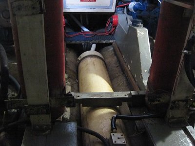
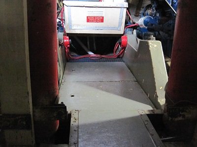
Well, I'll give a try at showing my PVC Pipe Holding tank. There are inlets from the heads on both ends. There is an outlet on the forward end for pump out and one on the aft end that is currently capped for pump out, I have thru hulls forward and aft for direct overboard pumping of the heads but I have removed the y-valves and capped the thru hulls for now so only way to empty the tank now is via pump out. We have not done extensive cruising in the boat yet but this has been adequate for week long trips with occasional pump outs at marinas every few days.

Kevin
 

Attachments

  • Holding Tank - Copy.JPG
    Holding Tank - Copy.JPG
    58.9 KB · Views: 286
  • Holding tank (3) - Copy.JPG
    Holding tank (3) - Copy.JPG
    59.4 KB · Views: 283
  • Holding tank (2) - Copy.JPG
    Holding tank (2) - Copy.JPG
    83.6 KB · Views: 52
  • Holding tank floor - Copy.JPG
    Holding tank floor - Copy.JPG
    59.7 KB · Views: 315
Last edited:
Kevin,
Thanks for posting the pictures. That tube is much bigger than I expected. I was expecting a smaller diameter tube. Possibly more than one somehow connected together giving you the 28 gallons.
I wonder if that was original out of the Prairie factory and if there are others with the big tube. I think the bilge location is good, keeping it low in the boat and out of the way.
I’m planning to have a single deck pump out for my tank located just aft of the port salon door. I’ve cut an access hole behind the cabinet just aft of the door allowing me to get to the underside of the deck. I’ll also put a 1” vent line through the hull using the same cabinet access.
Where is your pump out located?
 
Fog, no that was not a factory installation. The tank was fabricated and installed by the previous owner and his son. I think the boat was originally equipped with LectraSans and and pumped overboard. Those units are no longer on the boat.
 
New Hand Rail Project

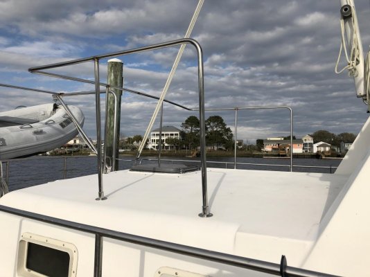
After moving the dink to the new stern davits we have a nice open area on the deck of the aft cabin. So we decided it would be a good idea to put some chairs and maybe a small table up there. But before we do that we figured adding some hand railing around it would make it safer.

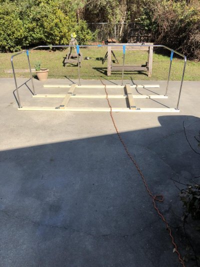
I drew up some plans, bought stainless steel tubing and stanchion bases, built a jig, had the tubing bent, and did a little metal fabrication.

My welder is busy until next so I have some time to get some feedback on this question. Should I have him weld the stanchions to the bases?

There is currently 2 set screws that secure the stanchion to each base. I thought it might be stronger if they were welded in place. However, I do like the idea that I could remove the railing without unscrewing the bases from the deck. In case it might need a repair or modification in the future.

Any thoughts?
 

Attachments

  • IMG_1353.jpg
    IMG_1353.jpg
    194.7 KB · Views: 59
Iirc, doesn’t the deck have some camber to it? I would think using the previous installed bases would be much easier to cut to height and ‘plug in’ the posts to the existing bases than trying to match the angle, bolt hole pattern to prevent more holes (leaks) in overhead.
 
Iirc, doesn’t the deck have some camber to it? I would think using the previous installed bases would be much easier to cut to height and ‘plug in’ the posts to the existing bases than trying to match the angle, bolt hole pattern to prevent more holes (leaks) in overhead.

Good point to having to match up the same bolt hole pattern for the bases if I had to repair or replace it. Thanks.
Yes the deck does have some slight camber to it. However, by leaving the bases secured to the stanchions when installing it I'm hoping the single railing across the back will take the appropriate shape.
 
Are the bases slightly angled? Or do the vertical pipes have to flex a little to make the base sit flat on deck? It would seem to me to leave the bases alone that are tight already. The trick is to make the verticals line up directly over them during fabrication. This is why during replacement it is often done with a few verticals using the clamp on connections on top. Easier to line up, and make it all fit.
 
Two thoughts. You can leave the rail flat, and cut the verticals to match the camber. Or flex the rail to (sort of) meet the camber. And as long as the measurements (green lines) between the Stantions are pretty accurate IMG_1473.jpgyou should be fine flexing them into the exit sting bases. Have you removed the old ones? (In the picture?). Or are they still installed? As long as the pipes fit in them. Just reuse the old ones.
 
Cappy,

Thanks for all of the suggestions. Since there is a very slight camber or crown in in this area, I'm going to use the flat jig I made in my driveway. I'm hoping once welded up, the single aft railing that transverses the deck in the direction of your green arrow will shape itself to the crown of the deck or stay almost straight.

This is a new install. There was no previous railing, stanchions, or mounts on this area of the boat to use for reference.
 
If you do have a problem with the camber, you can use thickened epoxy under the stanchions to conform to the deck camber. Cover the stanchion bases with wax paper and set the bases in the bed of epoxy and let it cure. Pull the bases off and then drill and properly bed the bases. The epoxy will fill the slight gap between the base and the deck. If you need to screw the bases down temporarily coat the screws with wax of Pam non stick coating so you can remove them after the epoxy sets up.
 
Last edited:
If you do have a problem with the camber, you can use thickened epoxy under the stanchions to conform to the deck camber. Cover the stanchion bases with wax paper and set the bases in the bed of epoxy and let it cure. Pull the bases off and then drill and properly bed the bases. The epoxy will fill the slight gap between the base and the deck. If you need to screw the bases down temporarily coat the screws with wax of Pam non stick coating so you can remove them after the epoxy sets up.

Thank you for the excellent suggestion. However, I'm hoping the railing will flex enough so I don't have to take this step. The camber is very slight so I'm keeping my fingers crossed.

Welding is scheduled for Monday. At this point I'm planning NOT to have the bases welded to the stanchions.
 
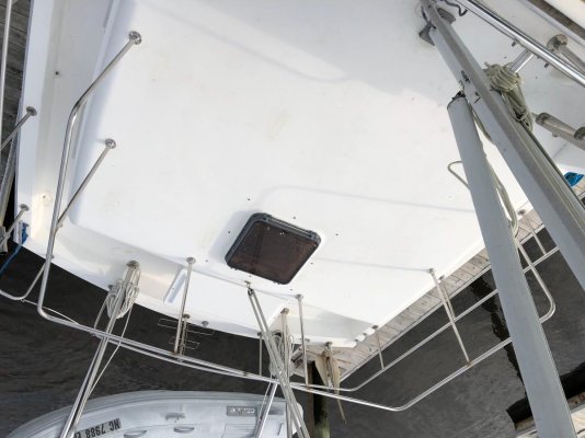
I was able to get the railing on the aft cabin installed. The rail across the aft section did not conform to the deck crown exactly as I had hoped, but I’m happy with the result, especially for a DIY job. Still need to polish up the welds.
 

Attachments

  • 3017E461-D747-46D1-ABE9-03E356F86F24.jpg
    3017E461-D747-46D1-ABE9-03E356F86F24.jpg
    111.5 KB · Views: 70
  • A2559929-04DA-4BB9-83BF-C239E4CB733F.jpg
    A2559929-04DA-4BB9-83BF-C239E4CB733F.jpg
    118.2 KB · Views: 66
Oops.
 

Attachments

  • EB0A9EF3-B8DE-49ED-9918-8E0D97F907CC.jpg
    EB0A9EF3-B8DE-49ED-9918-8E0D97F907CC.jpg
    112.4 KB · Views: 59
  • 398C972E-002E-430A-AE9B-BDD164DD7BC8.jpg
    398C972E-002E-430A-AE9B-BDD164DD7BC8.jpg
    109.7 KB · Views: 61
Sorry. I don’t know why the photos are still upside down after rotating them 180*.
First post with the new IPad.
 
The dreaded upside down photos. No idea why or how to fix it. About half of my photos are upside down. Glad you got the rail to fit.
 
Nice work! Maybe your camera is an Australian model?

Seriously, the "problem" is that iOS uses a non-standard format for rotating photos. It'll look find on your i-device, but nowhere else. My solution is to not own anything from Apple, but I realize that's not for everyone.
 
Should I have him weld the stanchions to the bases?

There is currently 2 set screws that secure the stanchion to each base. I thought it might be stronger if they were welded in place. However, I do like the idea that I could remove the railing without unscrewing the bases from the deck. In case it might need a repair or modification in the future.

Any thoughts?

You could epoxy them into the bases (in addition to the set screws). That should add considerable strength.

If you need to remove them in the future, just apply a heat gun to the base.

Just a thought. (OOPS! I see I'm too late.....)
 
Thanks guys. I had some trouble with posting photos some time ago when taken from my Iphone. However, after sending them to my laptop, rotating them, and then uploading them, they were fine. So I guess I’ll have to go back to that routine.

Boathealer, thanks for that suggestion. I’ll put that on the “to do” list.
 
Great results. Awesome project. Wondering how you bent the SS rail? Looks very smooth.
 
Great results. Awesome project. Wondering how you bent the SS rail? Looks very smooth.

Thanks Cappy. I had a fabricator do the 4 bends. The difficult part was finding a fabricator that could bend the SS rail in Wilmington, NC. Most of the fabricators in that area work with aluminum only.
 
Sorry if anyone suffered a neck injury. :flowers:
 

Attachments

  • IMG_1358.jpg
    IMG_1358.jpg
    111.3 KB · Views: 66
  • IMG_1359.jpg
    IMG_1359.jpg
    118.2 KB · Views: 60
Looks nice, much nicer right side up... My photos are usually upside down.
 
Looking at those pics reminds me: I've seen some Prairies with canvas between the stanchions on the trunk cabin ("sundeck") railing. I like the look, but I'm wondering what the extra windage will do. This thing already sails quite a bit.

Thoughts?
 
Looks nice, much nicer right side up... My photos are usually upside down.

Thanks. It appears that I will have to continue posting photos from my laptop. I tried to skip that step and post them directly from our new iPad. Even though both allow me to rotate the photos, the iPad photos still end up 180* out. :facepalm:
 
Looking at those pics reminds me: I've seen some Prairies with canvas between the stanchions on the trunk cabin ("sundeck") railing. I like the look, but I'm wondering what the extra windage will do. This thing already sails quite a bit.

Thoughts?

I agree with you on the windage issue. But not sure if I would like the look, especially in the corners.
If the canvas was only between the stanchions, the corners would be open. I think that would look strange.
To put the canvas in the corners around the radius you would need some attachment points on the deck with the same curve. That’s more work and expense. A better look, but not sure if it’s worth it.
Definitely something to think about.
Thanks for the suggestion. Now I’ve got another thing on my list. :facepalm:
 

Latest posts

Back
Top Bottom