Build it Yourself Temperature Panel

The friendliest place on the web for anyone who enjoys boating.
If you have answers, please help by responding to the unanswered posts.

steelydon

Senior Member
Joined
Aug 25, 2014
Messages
124
Location
USA
Vessel Name
Legacy
Vessel Make
Ocean Alexander 48E
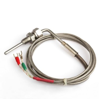
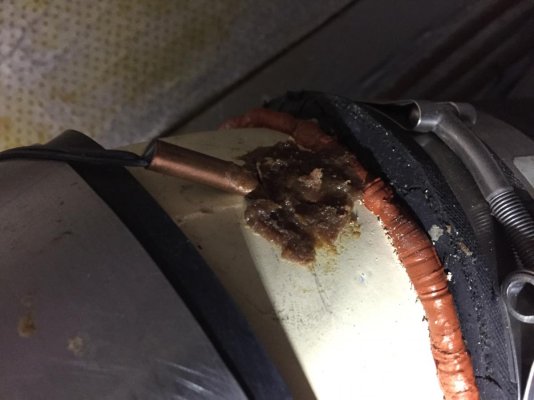
When I bought the Eagle in 2015 I did an extensive refit, at least for me. One big concern was system failures that could be mitigated if caught early. In an effort to accomplish this I built a temperature monitoring panel that monitors the surface temp of the oil pan, transmission, shaft seal and exhaust elbow at the water injection point. I purchase 4 digital gauges with audible alarms on ebay for around $20 each. I mounted them on a .25” black pvc panel and epoxied the sensors to the system surfaces. In the picture of the oil pan and exhaust elbow you can see I mixed in too much hardener and it kicked off too soon. However, they are well secured and not particularly visible, except to the members of TF.

Adjustments to the alarms were made after recording several daily outings with similar water and air temps (Average water 75 air 85). The alarms were set for 10 – 20 degrees above the average. Since there is a lot going on at the helm the audible alarms are useful as a warning.

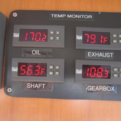
Also, every day the boat is on the water I do a 5 minute WOT and the panel displays, with remarkable consistency, how much the temperature increases in each system between 1,600rpms and 2,600rpms. If one system increased significantly out of the accepted range it would seem to indicate a problem in the making requiring some pre-emptive troubleshooting. The pictures of the panels below were taken this past weekend with water temps of 40 and air temps at 50. Although self-explanatory the photo with the lower readings is at 1,600rpms and the other is 5 minutes at 2,600rpms.

The operating range varies according to ambient water/air temps but the amount of increase at WOT stays about the same. I mounted my panel in the overhead console and for less than a $100 it performs a fairly valuable function.

Don
 

Attachments

  • IMG_1020.jpg
    IMG_1020.jpg
    58.4 KB · Views: 157
  • IMG_1021 (002).jpg
    IMG_1021 (002).jpg
    87.8 KB · Views: 169
  • IMG_7090.jpg
    IMG_7090.jpg
    102.6 KB · Views: 164
  • IMG_7092.jpg
    IMG_7092.jpg
    125.1 KB · Views: 163
That's really cool. Good work! Consider adding one for alternator temp if you can swing it. All that stuff is among the things I checked with a temp gun on ER visits.
I wouldn't stop doing ER visits with these, but would occasional shoot the temps again to see how they matched up.
 
Very cool! Love this idea and agree with caltexflanc it would bolster hourly trips to the ER with a temp gun.

I recently made the mistake of heading out with the upper helm key for the port engine in the "off" position which within a few minutes of leaving the dock presented as excessive engine temp from the lower helm port engine temp gauge. After shutting down the engine (and changing my shorts) a quick trip to the ER with the temp gun presented a "real temp" that disagreed with the gauge. A trip to the upper helm to get a third reading revealed the true issue.

A setup like yours would've been incredibly valuable and saved what might have been precious minutes from the diagnostics process in an actual overheating scenario.
 
Great job!

Most seem to come with short temp sensor wires..... did you find long ones or how did you extend them? Did that require a calibration adjustment?
 
You say you epoxied the sensors. Most epoxies wouldn't stand up to the temperatures you are seeing. Perhaps some kind of high temp epoxy?
 
Yes the sensor wires were too short so they were spliced to a 4 wire jacketed 22awg conductor similar to an alarm wire. The epoxy was a a high temp Loctite Hysol with some West System filler added in. I used whatever was handy which probably explains the gob effect.

Don
 
Given that your exhaust temps are under 100 deg F and from the location indicated in the picture, it looks like you are measuring the outside of the water jacket. If you lose raw water flow, you then have the insulation of the empty jacket to overcome before the alarm will trigger. Admittedly that might not take too long with it set at say 120 deg.

The other way is to epoxy the sensor directly to the exhaust hose. Measure the temps up and down the hose with an IR gun to find the best place. On mine, right after the mixer the hose is relatively cool as the raw water probably coats the inside of the hose. At just above idle (keeping the wake down inside the marina) the temp peaks in the 160 degree range about 18" below the mixer. Then another 6-12" lower it quickly drops to 100-120 as the water finally mixes sufficiently to cool it down.

Putting the sensor on the hose would more closely monitor exhaust gas temps. But it also would introduce the insulation of the hose before it starts to spike on loss of flow.

So, I don't know if a sensor located on the hose is any better. If you are a true experimenter you will warm up the engine, check the steady state temps, shut down, remove the raw water injection hose from the mixer and put it in a bucket and start up again and see which location responds faster.

I had that much energy in my younger years, no more!!

David
 
I can tell you with certainty, that if you loose RW flow at the exhaust elbow, both the hose and the metal riser/mixer will rise quickly and to high levels.

I think the temp monitors are a great idea and well implemented here. I will do a similar thing; and might look for a scanning unit, if available to save some space.
 
Dave, when someone speaks with “certainty” there is usually a story behind it. What happened?

Don
 
Ebay part numbers? Just to narrow down the search. Particularly if they are holding up well. Too many times I have purchased “cheap crap” that didn’t hold up long enough to make the labor worth while.
 
Dave, when someone speaks with “certainty” there is usually a story behind it. What happened?

Don

There is. :nonono: I was driving on a 90 mile leg across deep water, and someone shouted up "i see smoke out the back". It was the port side exhaust hose on the port engine with a blocked riser. The riser was just 3 years old. It plugged and started the hose burning from the inside out. Being a V engine, there was no overtemperature warning from the coolant, but pretty near had a engine fire non-the-less. Luckily, that system had both sides feed one muffler, or that could have been involved too. And that was inaccessable, below deck.
 
Ebay part numbers? Just to narrow down the search. Particularly if they are holding up well. Too many times I have purchased “cheap crap” that didn’t hold up long enough to make the labor worth while.


My ebay history does not go back to 2015 and the installation booklets are on the boat. They are called digital temperature controllers which may help with a search. Sorry I couldn’t be more specific.

Don
 
Would love to have that multiple display system. If anyone finds it on Ebay I'd appreciate hearing about it.

I've been searching but no luck
 
The pic at the top is all homemade I think...

I see plenty of $5 to $15 alarms...but you have to splice in longer temp probe wire and make up your own panel....or have one made.
 
These were not the gauges I used but are exact in their appearance. These are also controllers so they can be used to shutdown a circuit in an electrical application. 30 amp is a bit of an overkill for temperature readings and probably add to the cost a bit.

https://www.ebay.com/i/331355879933?ul_noapp=true

Don
 
Nice!!

I wonder if you could hook temp sensors up to a Noland RS-11 to get the data onto the N2K bus.

For the record, I refuse to do business with eBay any more. Turns out if an eBay seller disappears, you have no recourse through eBay or PayPal, short of waiting a month, then filling out a claim and waiting some more while they attempt to reach the seller.
 
That question is way beyond my expertise. Perhaps someone on TF could help with a response.

Don
 
If you intend to use "thermocouples"

Thermocouples use special extension wire and special connectors, and there are various types, and they are polarized. Type T and type K are the most likely for this temp range.

Although it is bad form to take one thermocouple and drive more than one device, it manytimes works. And sometimes, it causes noise to develop as a given display might generate a "thermocouple current pulse test" to test for an open connection.

If you use "thermistors" or Pt type sensors, different wiring rules apply.

It sounds (and looks) like the OP's sensors were NOT thermocouples. They appear instead to be one of the many that use a proprietary "one-wire" serial data connection.

Thermocouples are different, and would require a different input on any gauge/controller.
 
Some SONOFF modules have the option to connect temperature sensor probes and then you can write scripts on the SONOFF module to do whatever you want. They are WIFI enabled and could be put anywhere on the boat and consolidated with a small app on a tablet that would let you capture history, or drill down on previous data / running averages, etc.
 
In the past year, I saw a post on someone who had also made a monitoring system, that used 1 digital gauge, and a rotary switch that had multiple inputs, 9 if I remember correctly. Part #s were included. Did a search, but can’t find. It may have been elsewhere, but thought it was here. Anybody recall such a post?
 
I am in middle of building monitor and logging system for temps now.

http://www.trawlerforum.com/forums/s4/temp-monitoring-project-36667.html

Unlimited number of sensors on bus system. With data logging. I have being running a prototype now and it interesting to review temps over time.

With exchaust mixer if your sensor is on the metal you will see a spike in temp at engine shut down as the water stops and the heat soaks into mixer from hot exhaust. While running mine sits on 37c but rises to 60c at shutdown.
 
Don, where did you mount the temp sensor for the prop shaft? The stuffing box, I assume, but just want to confirm (in case I get a wild hair and replicate your setup).
 
Don, where did you mount the temp sensor for the prop shaft? The stuffing box, I assume, but just want to confirm (in case I get a wild hair and replicate your setup).


I placed the sensor on the clamp furtherest aft where the seal fastens to the shaft log. An article by Steve D’ Antonio stated that the temperature of the log/seal should not exceed seawater temp by more than 30-40 degrees. It seems logical that the loss or reduction of cooling water or any bind that may develop due to misalignment would increase the temp beyond that range.

Good luck

Don
 
Back
Top Bottom