Arduino Autopilot

The friendliest place on the web for anyone who enjoys boating.
If you have answers, please help by responding to the unanswered posts.

TG

Senior Member
Joined
Oct 17, 2012
Messages
197
Location
USA
Vessel Name
Tera Grace
Vessel Make
Californian 42 LRC
I thought I'd share a project I've been working on.

My initial intention was to automate my 1970's BENMAR 16B Autopilot by substituting the signal from the Binnacle with a signal generated using data from my Furuno Navnet. My reasoning was two-fold, I could retain the old system as a backup and, integrating into the old system with this method seemed to be the least invasive should I abandon the project.

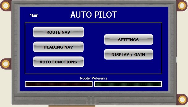
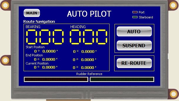
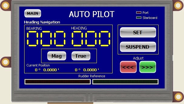
The ultimate goal was to be able to navigate a route or hold a heading. Secondly, the new device should be able to pick up the route automatically when set or cancelled on the chart plotter.

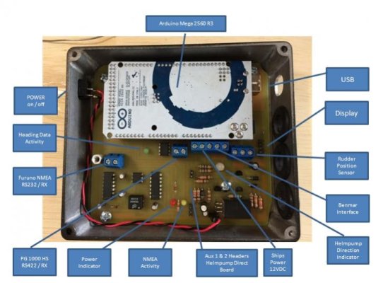
I chose the Arduino Mega platform for the usual reasons, it's inexpensive and there exists a huge knowledge base and developer network.

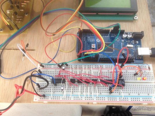
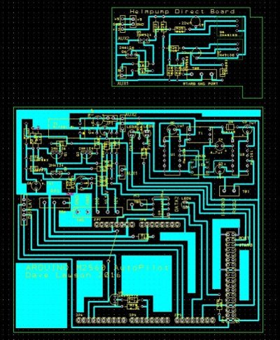
I did some initial circuit design to create the link from the arduino to the Benmar, basically converting the 5v logic signals to voltages the schmitt triggers on the benmar main board could use to operate the helm pump.

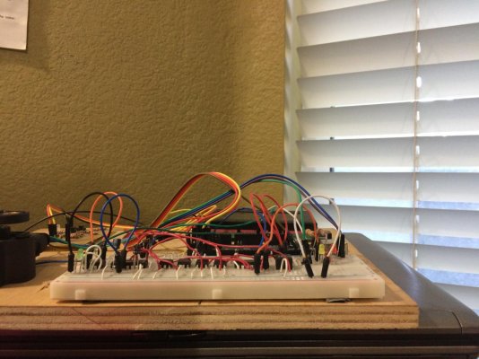
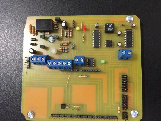
The small circuit board in the upper left of the photo below was my first attempt at interfacing with the Benmar. I connected it up and wrote a small program to send a signal to apply left rudder for 10ms then wait 10ms then right rudder 10ms and ran it in a continuous loop. I achieved success on the first attempt and boy was that exciting, I knew right then this was going to work.

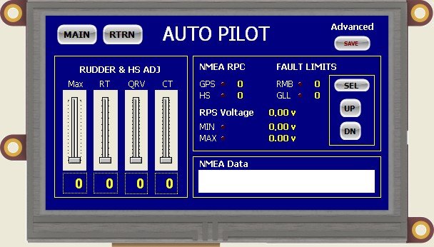
The next step was to develop the data interfaces. RS232 for NMEA, RS422 for the heading sensor. All of this needed to be converted to 5v TTL levels in order to be compatible with the Arduino Serial ports. I spent a lot of time designing and bread-boarding circuits at this stage, but ultimately settled on a Maxim 250/251 isolated transceiver chipset for the RS232 and a Maxim 487 transceiver for the RS422. (To Be Continued)
 

Attachments

  • IMG_0293.jpg
    IMG_0293.jpg
    150.9 KB · Views: 148
Well don't just leave us hangin'!!
You techno geeks just slay me>:eek::rolleyes:
Dave
 
Now that the data interface was worked out I focused on developing a rudder position sensor interface. I read where someone had used a Motorola Rotary Position Hall Effect Sensor so I obtained my own and set about to design the support circuitry. My first attempts were successful but the voltage readings experienced a little fluctuation. I resolved the issue by using the Arduino's 3.3v regulated output pin and feeding it back into the Aref pin.

At this point I had everything I needed to start writing code. I set up a serial link from my Furuno to my laptop and downloaded a stream of NMEA data that I could use to simulate the Furuno connection while working from my office.

The RPS is visible at the left of the image below. I would write code as I had time and carry the prototype back and forth from home to the boat testing pieces of code as I progressed.
 

Attachments

  • IMG_0062.jpg
    IMG_0062.jpg
    128.4 KB · Views: 186
Well don't just leave us hangin'!!
You techno geeks just slay me>:eek::rolleyes:
Dave

LOL! I'm working up to it. It's been operational for three months now and I have about 300 NM on it with great success.
 
Awesome. You seem to love problem solving with a pioneer spirit. Well done. I look forward to following your project.
Dave.
 
As the coding progressed I started to think about the interface component. I knew I didn't want to end up with a keyboard duct taped to a box with a 4 line LCD display.

I was really interested in using a graphic display but the Arduino really lacks the horsepower to process graphics and drive this type of display directly.

I found the solution in what is called an intelligent display. This type of display has its own onboard graphics processor and memory facilities. In fact this type of display could actually handle all of the work the Arduino is doing as well as the graphics. But of course I'm committed to the Arduino and don't really want to learn another specialized language.

I ended up selecting the 4D Systems intelligent uLCD-43DT with resistive touch panel. Features include; a 4.3" TFT 480x272 touch screen display, audio, micro-SD card connector, an expansion port along with a series of GPIO, I2C, SPI, and UART serial comms.

With this panel, there's no need for external buttons or switches as they can all be created on the display itself. The display is independently programmed and all the graphics and button processing reside on board. The communication with the Arduino is by high speed serial connection and it requires very little overhead so it's very fast.

Another and most important feature of the 4D System is the developer software. They have created a virtual drag and drop environment similar that is similar to creating a form in Microsoft Access. You pick an object be it a button or numerical digit or text box and drag and drop. The VisiGenie option will write the graphics code automatically which makes for some very rapid development possibilities.

I can envision using this display for any number of functions; Engine Monitor, Tank Level, Battery Monitor etc...

Enough said, if you are interested, search it out, I can't say enough good things about this display.
 

Attachments

  • uLCD-43D_s_02.jpg
    uLCD-43D_s_02.jpg
    50.8 KB · Views: 209
  • uLCD-43DCT-slide-3.jpg
    uLCD-43DCT-slide-3.jpg
    158.5 KB · Views: 220
  • IMG_0218.jpg
    IMG_0218.jpg
    126.7 KB · Views: 169
Very interesting project. I have built several Arduino-based monitoring and control devices for my boat, and have a long list of others that I intend to build as time permits. For display, I mostly have wireless connections (XBees) to a PC that runs Processing based code to display on any of my boat's displays. But I also typically have an LCD display at the source. None are as powerful as the display you use -- I am going to look that up and give it a try.

If you are willing to share your Arduino code, I would certainly enjoy seeing how you handled sensitivity and smoothing.

Thanks for your posts -- Rick

I do intend to share and post the code. I haven't played with XBees yet but I'm quite interested in looking at some wireless solutions. For now I'm taking a little break and just enjoying using the AP out on the water and making a bug list.
 
Enough said, if you are interested, search it out, I can't say enough good things about this display.

I notice that this display is available in a few different flavors, one of which is as an Arudino shield but that you recommend (or at least used) the one with a dedicated processor. Why did you not use the arduino version?
 
These are snapshots from the developer app of the various display modes and setting screens.
 

Attachments

  • AutoPilotD4.jpg
    AutoPilotD4.jpg
    49.4 KB · Views: 89
  • AutoPilotD5.jpg
    AutoPilotD5.jpg
    65.5 KB · Views: 122
  • AutoPilotD6.jpg
    AutoPilotD6.jpg
    63.6 KB · Views: 106
  • AutoPilotD7.jpg
    AutoPilotD7.jpg
    47.5 KB · Views: 110
  • AutoPilotD8.jpg
    AutoPilotD8.jpg
    63.6 KB · Views: 95
  • AutoPilotD9.jpg
    AutoPilotD9.jpg
    65.8 KB · Views: 100
I notice that this display is available in a few different flavors, one of which is as an Arudino shield but that you recommend (or at least used) the one with a dedicated processor. Why did you not use the arduino version?

I did use the arduino version, they all have the dedicated processor. I have the shield and used it for the initial development work. Later I consolidated all of the support circuits to a single 4 x 4 PCB and did away with the shield. I was making circuit design revisions faster than I could produce new PCB's so I worked with the breadboard until the final revision. The only thing I needed to replicate from the shield was the display reset circuit. Other than that the shield doesn't do much except provide a uniform way to connect the 5 pin ribbon cable.
 

Attachments

  • IMG_0292.jpg
    IMG_0292.jpg
    77 KB · Views: 132
  • IMG_0194.jpg
    IMG_0194.jpg
    170.8 KB · Views: 123
  • IMG_0193.jpg
    IMG_0193.jpg
    160.2 KB · Views: 151
  • AutoPilotD1.jpg
    AutoPilotD1.jpg
    53.7 KB · Views: 448
This is the final revision so far. I was going to build the Arduino circuit on the board but at $11 for a functioning board I decided last minute to expand the board and put headers to mount the Arduino as an add on board. If it ever goes bad I can just unplug and put a new one in place.

It was quite a challenge with routing the traces on a single sided board and so my terminal blocks are in the middle of the board rather than on the edge due to the last minute expansion to incorporate the Arduino headers.
 

Attachments

  • C1.jpg
    C1.jpg
    113.6 KB · Views: 121
Your work shows the amazing sophistication that a hobbyist can achieve in this area. It must be very satisfying!

Hopefully, I will have time to review the details for the display you recommend. What language (variant) is used to program the display? How is the IDE?
 
The IDE for the display side is basically an object oriented environment. In the background there is an underlying language 4DGL or 4D graphic language that is said to incorporate the best elements of C, VB and Pascal. There are several options for programming, from scratch, drag and drop with basic structure and then customize the code or let the Genie write the code for you. Of course writing from scratch gives more options and control.

On the Arduino side you just add the genie library and there are a whole host of commands based in C. The objects on the display are indexed in hex so referencing from the Arduino is done by object type and then hex index value. You can read or write data both directions.

I think you can download the IDE from 4D. Give it a test drive. You don't need a display connected.
 
Am I the only one here who is clueless? :confused::confused:
 
Before heading out to do sea trials I needed to mount the rudder position sensor. Right about the time I was working out fabricating an arm and linkage for the Motorola sensor, a dock mate installed a new Furuno AP and gave me a box of old autopilot parts from his ComNav system. In the box was a ComNav rudder position sensor and linkage.

I took it apart to see what was inside and confirmed it was configured as a voltage divider with a potentiometer and resistor. Virtually a drop in replacement for my AP design. I connected it to my prototype and reset the voltage endpoints and it worked perfectly so I replaced the cable with new and installed it on the boat.

The last hardware issue to deal with was mounting the display. I had a non-functional Furuno Navtex NX-300 that I considered using for the enclosure but it would require fabricating a new front cover and bazel. I ended up going with a stomp box enclosure instead and used the Furuno mounting bracket and knobs. The bracket was too wide so I cut 3/4" out of the center before mounting. For cabling I installed the 7 pin NMEA jack salvaged from the Navtex receiver on the new enclosure. I had a spare 7 pin Furuno cable so I left the connector on one end to connect to the display and pinned out the other end to connect to the 5 pin display header on the AP processor. Inside the display enclosure I pinned the back of 7 pin NMEA jack to the 5 pin header on the display.
 

Attachments

  • AutoPilotD3.jpg
    AutoPilotD3.jpg
    65.4 KB · Views: 127
  • AutoPilotD2.jpg
    AutoPilotD2.jpg
    53.5 KB · Views: 125
I have a Garmin AP. I know exactly how it works. You push a little button. Even Marin's dog can do it. :rofl::lol::dance:
 
Is that display daylight / sunlight viewable? Dimable?

How / when do we get a peak at your code?
 
TG,

Nice job even though you lost me. Nicely done.
 
TG: Is there a retailer (especially discount) that you recommend for that display, or is it best to go factory direct?
 
Is that display daylight / sunlight viewable? Dimable?

How / when do we get a peak at your code?

It's about like looking at an Iphone in direct sunlight. The screen does not have an anti-glare coating.

I believe technically it would not be considered sunlight viewable however it works quite well in daylight.

It is software dimmable with 16 increments. If you look at the snapshots I posted of the various screens one includes a slider for Rudder Gain and another slider for Dimming the Display. I anticipated these two functions to likely be the most accessed so I put them on their own page with minimal clutter.

If you message me your email address I'll send you the .ino file. I don't see a way to attach it here directly and it exceeds the size limit for a text file.
 
TG: Is there a retailer (especially discount) that you recommend for that display, or is it best to go factory direct?

I purchased mine direct from 4D Systems in Australia.

I wanted the Diablo16 instead of the Picasso graphic processor and was all set to order from Digikey.com but they listed the product incorrectly in their catalog. I sent in a request for them to review the listing and they confirmed they had listed the wrong product description and corrected it but I was in a hurry so I had already ordered direct.

Digikey is a great resource for components and I would highly recommend them.
 
Is that display daylight / sunlight viewable? Dimable?

How / when do we get a peak at your code?

For those interested, I dumped the code into a PDF. See Attached. If you would like to receive a copy of the .ino file then message me.
 

Attachments

  • AutoPilotCode.pdf
    135.2 KB · Views: 121
Thank you. I look forward to studying your code in detail (with the hope of learning new techniques, which won't be hard since I am entirely self-taught), but have glanced through it and recognize that it is well commented -- and much longer than any Arduino code I have ever written. Does it fit on an Uno?
 
Thank you. I look forward to studying your code in detail (with the hope of learning new techniques, which won't be hard since I am entirely self-taught), but have glanced through it and recognize that it is well commented -- and much longer than any Arduino code I have ever written. Does it fit on an Uno?

The compiled size is just over 33K on the Mega so it wouldn't fit on an UNO. I also use all four hardware serial ports on the Mega and so that would be a limitation on the UNO.

Serial 0 = USB - Programming and Port Monitor for Debugging
Serial 1 = NMEA - Chartplotter
Serial 2 = NMEA - Heading Sensor
Serial 3 = Display / touch panel
 
Love this project!

I did a very similar thing, using a Raspberry Pi running OpenCPN to feed Autopilot and GPS NMEA sentences into a PID loop to determine course corrections... it worked fine at trawler speeds in open spaces, but ran into problems at even 10 kts due to GPS variances. I had toyed around with a digital compass to try to correct it, but life happened and I moved on.

I'm selling my boat so I took it all off so the next owner wouldn't get himself into trouble -- it wasn't ready for public consumption at the state it was in. I learned a lot about what is in the internals of auto-pilots.

The Raspberry Pi would be a great platform to use. At least you'd be able to achieve double precision math. The single precision of the Arduino Mega has presented some challenges.

The problem with not having a heading sensor is you don't know the bow direction and therefore applying correction is a bit sloppy along with the inherent GPS heading sloppiness. Consider that you could be cruising in reverse and the GPS wouldn't know the difference. It only knows the direction of travel, not the orientation of the vessel. The other issue is at least in my case, My Chartplotter sends burst of NMEA data 1 time / second. The Heading Sensor sends Mag Heading 10 times / second. I can navigate 10 times more efficiently with a heading sensor with RS422. With AD10 it could be increased to 100 reads / second.

The same thing applies to not having a rudder position reference. Yes you can make it work but you lose accuracy. It's much more precise to tell the rudder exactly how much angle to apply then to tell it to start moving and wait to see if it moved enough or too much.
 
Last edited:
Back
Top Bottom