DonnyP
Veteran Member
Guys,
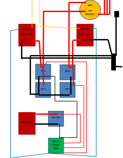
Attached is a diagram of my batteries as setup by the PO.
Problem #1 in my system is my ongoing quest to get a qualified mechanic to actually show up and work on my generator when they say they will. So that leaves me with shore power and my battery charger or engines for now.
Problem #2 is that I really cant see how my alternators are charging the batteries??
Problem #3 Both engines are wires straight to a battery, each will start regardless of battery selector switch.
Problem #4 I'm really not sure what the switch is doing. (labeling on switch is also from PO).
Problem #5 Do I need the negative cable connecting Batt's 3 & 4? Do I need the Negative from the battery charger to the gen battery and Battery 1? Or just to Battery 1..or just to the negative bus bar on the stbd side?
Thanks in advance for answers, suggestions, questions.
The charger is an older model, 60Amp, with 3 positive legs. The alternators are Prestolite 65Amp each. Twin Ford Lehman 120HP. Onan 6.5KW gen (work in progress).
-Donny