Lot's of comments already so sorry if I repeat.
- I don't think it's complicated at all, just extensive. No problem with that if it's what fills the need.
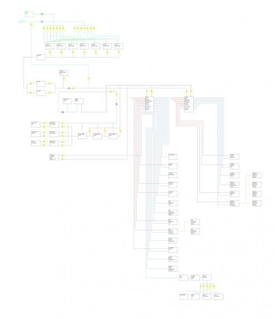
- I think the central manifolds with home run plumbing is the ideal, and if you have space for the PEX tubing for all of it, that's great.
- I'm familiar with the Varga manifolds for heating system. Just be sure they are rated for drinking water, e.g. lead free.
- I think you said all the tanks are side by side? That will be important to ensure they fill in tandem, and drain in tandem. Each tank will need to be individually vented. They could go to a common vent, but be absolutely certain that there are no droops or low points in the vent lines. Otherwise when you overfill the tanks, which at some point you will surely will, and the water all comes out the vents, you can't end up with a water trap in any of the vent lines. Otherwise the unvented tank will never fill properly.
- I assume you will normally leave the valves open joining the tank draw lines? That will allow it to act as one large tank rather than 7 small tanks.
- I agree that 210 gal is very light, but if that's all you can fit, so be it. Just be sure your watermaker is in good shape or you are near to docks with good water.
- I think in most cases you will want all the valves open from both the fill manifolds so that all tanks fill more or less together. To make it easier to turn the dock water feed to teh manifold on adn off, I'd put a valve on the feed line. Then in normal operation you will only have one valve to operate to fill the tanks from dock water, and one to shut off if you want to run directly off dock water.
- I don't think you need a check valve coming from the watermaker. I would only do that if the watermaker installation instructions specifically call for it. Most of the watermakers I've dealt with want no restrictions between the WM and the tanks.
- I would put the check valve on the other side of the accumulator. Otherwise it can't absorb expansion and contraction in the core of the water system. It also allows the accumulator will be operative when on dock water. That part isn't essential, but will aid in quick flow demand changes
- I would put a pressure regulator on the dock water inlet. I have seen docks with over 100 psi of water pressure. So much that it blows out hoses. You don't want any chance of over-pressurizing the system in the boat. In fact, a lot of people recommend against a direct dock water connection for just this reason, and because if something does fail it could flood and sink the boat. Without a dockwater connection, the most water that could leak into the boat is your water tank capacity.
- You are missing a cold water connection feeding the hw heater.
- You should install a tempering valve on the HW heater outlet.
- The thermostatic valves don't make sense as drawn. I think you intend each to open/close based on temp of the associated heat exchanger? And I'm not following the intended flow of water through the HW heater and heat exchangers. Is there a circulating pump somewhere?
- Check to be sure you can get an ABYC compliant tankless propane water heater. Historically they don't exist, but that may have changed.
- Will the boat have diesel heat? If so your look at tying that in
- If you move the check valve by the accumulator then you won't need a second expansion tank for the HW heater. The other check valves are probably not needed either, and may cause over pressure issues, but it's hard to say until I undersand how that part of the system in intended to work.
- Consider using one of the unused ports on your water manifolds for a compressed air inlet. That will make it really easy to blow out any outside fixtures when the weather gets cold.
- Since you are starting from scratch, consider installing a hw recirculator to get more or less instant hot water at the taps. You could only do it as far as the distribution manifolds, and that bmay or may not be enough given how everything lays out. You can run the pump continuously, put it on a time-of-day timer, or run it on demand. I prefer the on demand approach to save power and heat loss. We have call buttons in the bathrooms, galley, etc. One press turns the pump on for a few minutes. A few seconds later, you can turn on the faucet and have hot water. With your small tanks, this will help a lot vs running the tap for a long time waiting for hot water. These can be deceptively tricky to do, but I can likely help if you want to go down that path.
- I strongly recommend insulating the HW PEX if space will permit. I have had a couple of boats and houses where there was cross heating of the cold water lines. Instead of having to run the water for a long time waiting for hot water, you had to run it a long time to get cold water. Wasting water like that on a boat isn't good.
- I assume the Vega manifold outlets are all valved?
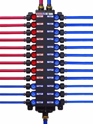
The manifolds are Viega manabloc manifolds. Wish they would have expnsion fittings, but only crimp

All the tanks are side by side and same height etc. So easy to treat them equally and as one tank. All valves will be open to them, and it will work into filling and usage as one tank.
I wish I could fit more tanks, but I cannot. The water maker is of good quality and size. It is a sea recovery unit. I could put tanks elsewhere for more, but at that point, it is extra space, complexity etc for just a little bit more of a reward, so I ruled it out.
I put the check valve on the water maker so that the rest of the system would not force into the water maker. Did not know if it needed it or not.
The water fill would not be a pressurized system. It is just a deck valve which you can put a hose into. and it is open, so no pressure build-up. I do not want to keep a hose pressurized in the system at the dock. I have heard horror stories from it, and figured it best not to do that.
I will check out what tempering valve is, as I have never heard of one.
The thermostatic valves are essentially three in series. The heat exchanger goes into them. I know I can get away with one, but I figured having three is extra redundancy, and safety, to make sure no scolding water gets into the system.
The heat exchangers valves are designed to allow just one to be used. It is done as such as each engine for propulsion has one, and one of the 5.5kw Genset. I figured those would be the three most likely to be running.
All of the ball valves, I know seems a bit much, but the vast majority will be in a select few areas, essentially viewing them as on a board. All of the valves for the heat exchangers and thermostatic valves will be in one area. For water tanks in one area, etc.
The tankless water heater would be outside if it is used at all. It will end up being put in towards the end after everything is tested, and I hope I will not need to install to be very frank.
The compressed air inlet is an incredible idea!!!! I will be glad to do so, as it really will make my life substantially easy. Especially since I am permanently installing a compressor onboard.
For moving the check valve, let me look at it and come back with something for additional input from you.
No diesel heat onboard. I was looking at a tankless diesel water heater, but it is a lot of cost for not much gain. And heat interior-wise, the 6 self-contained units I figure are good enough. Diesel would be nice, but would add more complexity. And since its intended grounds are normally so-cal, not tons of use.
The HW recirculator is a slick idea as well, especially with a button to control it. Would love to get more input on this.
Did not think about insulating pex hot lines. Though I think that is another great idea!
I have also attached a photo of one of the manifolds I am using.