2x30A shore to 50A on board?

The friendliest place on the web for anyone who enjoys boating.
If you have answers, please help by responding to the unanswered posts.
Perhaps if the OP would post pictures of cable ends , cable adapters and pedestal, then there would be less speculation. It has become apparent that the written explanation is being interpreted in multiple ways resulting in different suggestions.

I think most people do not understand the difference between 50a 125v and 50a 125/250v. 50a 125v is old school and only seen at older marinas. Now days it wouldn’t surprise me if the majority of boaters have never seen 50a 125v.

I bet there a lot of TF’s looking at Twisted’s diagram and seeing the physical difference for the first time.

If you have been around long enough you will remember 20a 125v sockets.
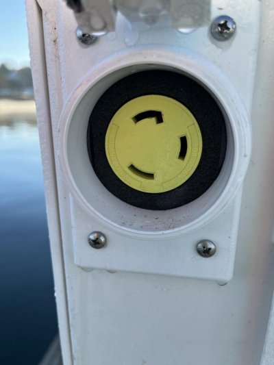
Yes I do, thanks for the reminder. That was the solution when 15 was not enough for many stock boats. I think they just replaced the breaker size & outlet as wiring size outdoors could handle it. (guess that changed too)
 
Let me post some photos.

IMG_0082.jpgIMG_0084.jpgIMG_0085.jpgIMG_0086.jpgIMG_0089.jpgIMG_0090.jpg


Thanks. Pictures are worth a 1000 words, and how many posts on TF? :)


The shore pedestal was at your old slip, correct? It shows a single pole breaker, and a 50A 120V outlet. All that's consistent.


And your boat's inlet and shore cable are both 50A 120V.


You have mentioned that your new slip has 30A 120V outlets and that thee aren't any 50A 120V outlets. But I don't know if it was ever asked or said whether there are any 50A 120/240V outlets nearby? I have perhaps assumed there aren't, but should ask explicitly.
 
As you can see on the pictures, the boat is wired for 50A/125V. I use an adapter to convert the 50A down to 30A, which connects to the 30A cord to the 30A pedestal plug.

It seems that the boat used to have two inlets prior to the 50A upgrade, when the isolation transformer was installed. I suspect it was 2x30A before, but I have no documentation on that.
Reversing this to two inlets again is possible. Can that be two 50A inlets?
Can the isolation transformer be wired to two 50A in/out connections?
Can the switchboard be wired with two 50A buses?
The boat used to provide 240V through the generator, which has a separate panel for this. This panel was wired into the main switchboard to supply 240V for the dryer I used to have. The dryer is gone now, so there is no 240V connection as of now.

Based on the comments, it seems that the only safe solution here is to covert the shore connections back to two inlets again. Ideally, it should be two separate 50A/125/250V inlets. I don’t know if that is doable in my present wiring solution? Again, having protection from the isolation transformer is important.
 
Post 63 pedestal, is that the first one or the one you are at now.
Guessing new location, which explains you plugged into a 50 directly before and now only have 30 available. This is what I was following, and unknown to me an available twin 30 male to 50 is frowned upon for safety reasons, even though being for sale.
 
Thanks. Pictures are worth a 1000 words, and how many posts on TF? :)


The shore pedestal was at your old slip, correct? It shows a single pole breaker, and a 50A 120V outlet. All that's consistent.


And your boat's inlet and shore cable are both 50A 120V.


You have mentioned that your new slip has 30A 120V outlets and that thee aren't any 50A 120V outlets. But I don't know if it was ever asked or said whether there are any 50A 120/240V outlets nearby? I have perhaps assumed there aren't, but should ask explicitly.


I am good at posting pictures here. Just ask and I’ll post it.

The photos you see show the present situation. I am not interested in the 50A/120/240V pedestal. It is far from my boat at my present slip. Yes, I used to have that at my previous slip, but that is gone.

Right now, I am trying to see a fairly manageable conversion back to two separate inlets/circuits and preserving the protection from my isolation transformer. If the two inlets conversion is possible, I would connect to two individual pedestals with invisible cables, inlets. The switchboard would be divided into two AC branches. Each branch would handle a set of loads separately.
 
Post 63 pedestal, is that the first one or the one you are at now?


Post #63 is the present situation.
I can reach two separate pedestals like this. I have enough cables to do so, but no adapter would combine the two pedestals safely.
The only solution is to re-create the two connection setup again.
At this point the main question is; how the insulation transformer can be part of this?
 
Looking for an answer of why the 50 amp isolation transformer cannot support in phase two 30 amp cords. The main breaker on boat past the transformer is 50 amp? (correct), then the transformer is not asked to deal with more than 50.
The out of phase on two outlets would cause a short and trip breakers unless there can be an onboard protection built in to ensure in phase at two 30 amps.
JMO.


Got it. That make sense. In phase 2x30A will flip the breaker of 50A.
What if the draw is not more than 50A? Or only occasionally and the breaker will be pushed back, once the extra load is removed?

The onboard protection for the 2x30A out of phase connection is the sophisticated and expensive one?
 
Not sure exactly how you think of it, but a 50A 125V system isn't really an upgrade from 2-30A connections. You are losing 10 total amps (approximately as the math is different is you keep to the lower continuous duty rating) and maybe other depending on system design.

If the only time you need more than 30A is for winter space heaters, to me the most simple way would be add a 30A power inlet with a breaker that goes to a separate outlet or two dedicated to just the space heaters. Of course you can use it all year for other things too. Then it wouldn't matter if the separate service was in or out of phase.....basically like running a permanently installed heavy duty extension cord.
 
Last edited:
Got it. That make sense. In phase 2x30A will flip the breaker of 50A.
What if the draw is not more than 50A? Or only occasionally and the breaker will be pushed back, once the extra load is removed?

The onboard protection for the 2x30A out of phase connection is the sophisticated and expensive one?

Perhaps now that it is narrowed down to either having marina install a 50amp 125v OR a solution found to automatically disconnect above 120 volts at least one of the lines. This is not normal.
This is only a thought but what if two inlet breakers are added, 30 amp each to feed load single from the cords. They will surely trip on 240, but is this a smart solution.
 
Last edited:
Perhaps now that it is narrowed down to either having marina install a 50amp 125v OR a solution found to automatically disconnect above 120 volts at least one of the lines. This is not normal.
This is only a thought but what if two inlet breakers are added, 30 amp each to feed load single from the cords. They will surely trip on 240, but is this a smart solution.

I'm not understanding this question.

Leoka is caught between two worlds. The expensive and likely the most versatile way would be to convert the Boat to 50a 125/250v. His generator is already set up for it. He would need to make a decision on whether he wanted a 240v capability or just two 125v panels. Either decision could result in needing to replace the Isolation Transformer. Possibly could be done with the current IsoTrans depending on what it is capable of.

AS Psneeld said, the simplest and likely cheapest move to make would be adding a second 30a 125v line and a 30a IsoTrans dedicated only to the heat. It could be wired with a switch that would allows it to choose from the 50a 125v or the generater should the next slip have a 50a 125v or 50a125/250v socket.
 
Leoka is already set up (has 50 amp isolation transformer, 50 amp main breaker) for 50 amp 125 volt but only has 30 amp 125 to plug into. 30 amp is not enough for his needs.
 
I would get rid of the 50 amp 120 volt inlet entirely. They are an oddball out of date setup. I would convert to two 30 amp inlets. It would be a lot of work but fairly easy to do. Then you have the connivence of being able to plug into 2 30 amp dock plugs or with a Y adapter plug into a 50 amp 240 volt dock plug. That is what is on all the docks around here, I have never seen the 50/120 on any docks here. Maybe where you boat it is different but those will likely go away when the docks are upgraded as they will be eventually.

First I would see what brand and model isolator you have and what it is capable of doing. Then you would need new inlets (SmartPlug is the only way to go), a new main panel and a new isolator maybe (depending on what the one you have now is capable of doing). If the isolator can support 2 30 amp inlets then you are good. If not it should support one 30 amp inlet so you would have to buy another isolator for the second 30 amp inlet. I really like Blue Seas equipment so check and see if they have anything that would fit your needs, if not maybe Paneltronics.

Or you could convert the boat to 50 amp 240 volts but since your marina doesn’t have that I would not go that way.
 
Last edited:
It seems that the most economical solution is to add another connection with 30A, wire it to a new panel just itself, and connect some of the load to this panel. An isolation transformer could be included, if it is used regularly. (30A).
This would be totally separated from the existing setup. This would allow me to use two separate connections. Or, just the 50A setup I have now, if the marina upgrades the pedestal to 50A some day.
 
Or you could convert the boat to 50 amp 240 volts but since your marina doesn’t have that I would not go that way.


All the existing 50A pedestals in the marina are brand new 125/250V. My boat needed an adapter to connect to my 125V inlet.
 
I would get rid of the 50 amp 120 volt inlet entirely. They are an oddball out of date setup.


I would, too. I just don’t know if my isolation transformer can take it? It shows on the photo that it is 120v.
I don’t know, if a 125/250 inlet can be wired to it directly?

IMG_0211.jpg
 
Last edited:
I would, too. I just don’t know if my isolation transformer can take it? It shows on the photo that it is 120v.
I don’t know, if a 125/250 inlet can be wired to it directly?

View attachment 134003

Well lucky you. That is a 50a 125/250v isolation transformer. I would definitely switch to a 50a 125/250v socket and then use a two 30a 125v to one 50a 125/250v Y adapter.

You will still need to wire in the second panel like previously mentioned and move the heat sources to this panel. You just don’t need to buy a second isotrans.

I am going to recommend you consult a marine electrician on this. You still have some decisions to make.
 
Well lucky you. That is a 50a 125/250v isolation transformer. I would definitely switch to a 50a 125/250v socket and then use a two 30a 125v to one 50a 125/250v Y adapter.


Well, if that is the case, I do NOT need a second inlet. I do have the Y adapter for the the two 30A connections already. If the inlet is replaced to 125/250 with 50A, that is plenty enough for me, even with the heaters on.
 
You will need a 50a 125/250v power cord as well. This will get you 60a total on board but only 30a to each panel.

Hopefully your splitter is one of the smart ones. The two 30a sockets need to be out of phase or you will overload the neutral (very dangerous) or screw up the isolation transformer.

You might want to include a picture of your splitter.
 
You might want to include a picture of your splitter.


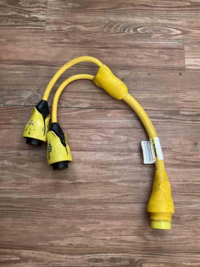
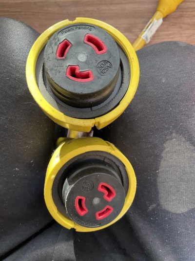
I don’t know how smart it is, but here are the photos.
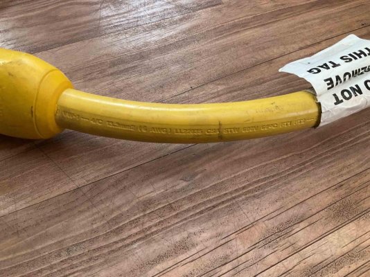
Marinco EEL 2x30A to 50A/125/250V adapter.IMG_0215.jpgIMG_0214.jpgIMG_0213.jpgIMG_0212.jpg
 
This is just an outline of what you would need to do.

Y splitter as mentioned above.
50a 125/250v power cord
50a 125/250v socket for boat
Wire to a master breaker that trips all 3 poles.
Wire to transformer
Wire from transformer to panel 1
Wire from transformer to panel 2
Build panel 2
Move heaters to panel 2
 
Notice, this device auto senses correct wiring.


After looking at the instructions, I think there is a problem. This adapter requires the two 30A receptacles to be on the different phase. This is not an issue, when the pedestal has two 30A receptacles next to each other. My situation is different. Each pedestal here only has one connection of 30A. So, I need to connect to two separate pedestals. I suspect that these single plug pedestals are on the same phase and this adapter will not function.

I think we are back to the additional inlet on board idea.
 
That is very possible but not necessarily a fact. Still, bringing a second line on board and keeping it completely separate ftom the current system is going to be the cheapest solution.

Its not a bad plan as it doesn't prevent you from upgrading to 50a 125/250v in the future. Adding an isolation transformer to the the 30a line would be potentially wasteful if you up graded. The isolation transformer wouldn't really be needed as this line would not tie into any of the boats grounding systems. Just don't ever add a battery charger to the second line. You will need to run ground wire specifically for the heaters. You would not want to tie into the existing ground wire system.
 
It looks like (from the label) your current Isolation Transformer's Input is limited to 120V, and single phase.

If so, it will not work with 240V split phase supply, nor will it produce 240V split phase.

Your quickest remedy remains a separate 120V 30A supply from the other pedestal that you keep entirely separate from the existing boat wiring. New inlet, breakers, wiring, buses, branch circuits breakers and branch circuits as usual. Use it at a current draw of no more than 24A if the load is for more than about a minute.
 
That is very possible but not necessarily a fact. Still, bringing a second line on board and keeping it completely separate ftom the current system is going to be the cheapest.


Heaters are not needed as much, since I have a good diesel furnace in place. My issue was with the water maker. The high pressure pump draws about 8-10 amps. Plus whatever else is running.
Wiring the ground separately will not be problem.
 
It looks like (from the label) your current Isolation Transformer's Input is limited to 120V, and single phase.

If so, it will not work with 240V split phase supply, nor will it produce 240V split phase.

Your quickest remedy remains a separate 120V 30A supply from the other pedestal that you keep entirely separate from the existing boat wiring. New inlet, breakers, wiring, buses, branch circuits breakers and branch circuits as usual. Use it at a current draw of no more than 24A if the load is for more than about a minute.


I think that will be my remedy. 24A is a valid number.
 
Back
Top Bottom