2x30A shore to 50A on board?

The friendliest place on the web for anyone who enjoys boating.
If you have answers, please help by responding to the unanswered posts.
Ask the marina to change your pedestal?


Could be simple. Might not even charge you, but if they do, might not be much.


-Chris


I did. They have no plans to do it.

Maybe I’ll ask how much it would be, if I pay for it?
Again, it is not life and death issue. I can manage as I am.
 
That appears to be a splitter, taking a 50A 120V shore outlet and splitting it into two 30A 120V sources. He wants to do the reverse, and you can't do it without violating countless wiring and safety codes
OK that might have been the wrong one but here is exactly what he is looking for -I believe unless I'm off again. This one does show the end contacts...
2 - 30A male to 50A female (3 wire - 120V)

https://www.amazon.com/Parkworld-Co..._bs_3398761_sccl_48/142-6237289-8756842?psc=1
 
Last edited:
Agree...
I'm wrong again! 0 for 3 and a strike out
Sorry for the confusion
 
As I mentioned in post #19. His best option is probably to run a second independent 30a line into the boat just for some heat.

It can be done very inexpensively as long as it’s kept independent of the primary system. He could put the heaters on a rotary switch that allows them to either source the 50a or 30a shore power. This would give him the best of both worlds.

The second line would not be on an isolation transformer. However, with just the heaters on the second line you could avoid the need to combine the grounds between this system and the rest of the boat. If you added a rotary switch make sure the grounds get switched as well.
 
Was just going to say the same thing as Ranger... Just convert the 30a pedestal to 50a and not have to worry about plugs/adapters/cables... Shouldn't be more than $500 to change you out...


I don’t know. If I spend my money, I’d rather improve my boat and not the marina. Besides, the marina is in the process of changing ownership, so nobody knows what is coming.
I am seriously considering the upgrade on my boat to two circuits, instead of one.
 
That panel lets you select between two shore cords and a generator, but you can only use one at a time. There is no provision to combine anything.


You only have two choices:


What if there is 3rd choice? More money, but my boat will benefit from it.

I spoke to Paneltronics and I have the answers. If I buy their panel for dual shorepower, I can connect two individual pedestals. This will require me to do some work on the existing switch board and split the present AC sub panel into two. This way, each connection on the Paneltronics can supply a partial AC branch. Optional 50A breakers can be chosen at ordering. I will need to buy and install another 50A/125V inlet and do the wirings.
This setup should not violate any codes and will give me more flexibility.
The panel in question also has a parallel switch, which allows to share one connection between the two AC branches, if only one connection is available from the dock.

What do you think?
 
As I mentioned in post #19. His best option is probably to run a second independent 30a line into the boat just for some.
The second line would not be on an isolation transformer. However, with just the heaters on the second line you could avoid.


Your suggestion is valid and it could be a solution. However, this is not just about the heaters. I have a water maker, portable ac, other appliances. Those draw enough to dim the lights, or flip the breakers, if multiple are on.
I am thinking long term. I might not be at the present marina forever, and flexibility or extra load options would be nice to have. You will never know when it is needed, and it would be more pricey to do upgrades like this in another country. Yes, it is not cheap to upgrade, but it can pay off sometimes in the future.
 
As I mentioned in post #19. His best option is probably to run a second independent 30a line into the boat just for some heat.

It can be done very inexpensively as long as it’s kept independent of the primary system. He could put the heaters on a rotary switch that allows them to either source the 50a or 30a shore power. This would give him the best of both worlds.

The second line would not be on an isolation transformer. However, with just the heaters on the second line you could avoid the need to combine the grounds between this system and the rest of the boat. If you added a rotary switch make sure the grounds get switched as well.

Respectfully wish to ask does your suggestion pass ABYC.
You said the splitters that stayed outside the boat were against the rules, how possibly can a bypass of the isolation transformer panel and reverse polarity be acceptable.
 
Agree...
I'm wrong again! 0 for 3 and a strike out
Sorry for the confusion


No worries. None of the product descriptions for adapters make it easy, and ParkWorld selling a product that violates all North American electric codes doesn't help either.
 
Your suggestion is valid and it could be a solution. However, this is not just about the heaters. I have a water maker, portable ac, other appliances. Those draw enough to dim the lights, or flip the breakers, if multiple are on.
I am thinking long term. I might not be at the present marina forever, and flexibility or extra load options would be nice to have. You will never know when it is needed, and it would be more pricey to do upgrades like this in another country. Yes, it is not cheap to upgrade, but it can pay off sometimes in the future.

Now you’ve done it. You let Pandora out of the box.

Before you spend any money you need to determine if you are a 110v or a 220v boat. Then you will need to decide if you will continue with Isolation transformers. There are a lot of ways to skin this cat now.

When I got my boat it was a 50a 125v boat. I converted it to a 50a 125/250v boat. I kept everything on my boat 110v. My dryer is 220v but it has a dedicated transformer that changes 110 to 220 just for the dryer. I put my washer/dryer, heat pumps and resistance heaters all on L2. Everything else is on L1.

If I have a 50a 125/250a socket available I am golden. If there is only a 50a 125v socket available then I need to fire up the generator for heat and laundry. With two 30a 125v sockets I can get by but I can’t do heat and laundry at the same time.

I could have done paralleling between the two. I just felt like the number of times that I would need heat and laundry with out a 50a 125/250v socket would be few and far between so I decided to keep things cheaper and simpler.
 
That panel lets you select between two shore cords and a generator, but you can only use one at a time. There is no provision to combine anything.


You only have two choices:


What if there is 3rd choice? More money, but my boat will benefit from it.

I spoke to Paneltronics and I have the answers. If I buy their panel for dual shorepower, I can connect two individual pedestals. This will require me to do some work on the existing switch board and split the present AC sub panel into two. This way, each connection on the Paneltronics can supply a partial AC branch. Optional 50A breakers can be chosen at ordering. I will need to buy and install another 50A/125V inlet and do the wirings.
This setup should not violate any codes and will give me more flexibility.
The panel in question also has a parallel switch, which allows to share one connection between the two AC branches, if only one connection is available from the dock.

What do you think?


It's a variation of option 2 that I offered, and that others suggested too. You just need to plan out how it will work in conjunction with your isolation transformer, how you will provide galvanic isolation for the new shore circuit, and how you will replace/rewire your electric panel to work with everything. It's a better long-term solution, but I think probably a lot of work. Buying the panel from Paneltronics is the easy part.


As part of planning this out, I'd suggest looking at replacing your existing 50A 120V shore inlet with a 50A 120/240V inlet rather than adding a second inlet. Then most of the time you can operate with only one shore cord instead of two. Plus 50A 120/240 dock power is much more common than 50A 120V. On the boat you can still split it out into two separate 120V circuits as you were previously planning.
 
Ask the marina to change your pedestal?

Could be simple. Might not even charge you, but if they do, might not be much.

-Chris

I agree, just ask the marina to change the fuse on the pedestal or change the complete pedestal. I have seen that done in my marina for the boat next to me, took them one morning and that was all.
Most likely they could just get away with changing the main circuit breaker from 30 A to 50 A. I would be surprised if the wiring cannot take the 50 A.
 
Did you check voltage yet?

If hot to hot is zero you have (2) 120 volt circuits. Verify by hot to neutral 120 volt.

If hot to hot is 240, then you'll have to split the loads in the boat.
 
Last edited:
You can use your standard twin 30 amp y to fifty amp plug AS long as the 2 30 amp plugs you are using are on the same leg. The adapter will not know the difference. Giving you only 125volt to the boat. If you don't know how to figure that out , call the marina they will have a wiring diagram and tell you witch posts to use. Make sure they understand or you will fry stuff.

Most posts in a marina with 2 30 amp plugs on the same posts are 2 110 plugs on the same leg. But check with the marina.

If you plug your 2 30 amp cords into the y and test the back side of the y , you can test to see if you have 220 or 110
 
So, just to clarify:

There are two major components, Pedestal wiring, and boat wiring.
So that gives us 4 possible scenarios, below:

1. Pedestal = 50a 125/250v, shore power cord and boat = 50a, 250v:

You will have two 125v wires, out of phase, so you can run any 220v appliances if so wired, correct?

2. Pedestal = 50a 125/250v, shore power cord and boat = 50a, 125v:

If you plug in the only change is that the two 125v wires will be in phase, so you cannot run any 220v appliances you may have, correct?

Conversely,

3. Pedestal = 50a 125v, shore power cord and boat = 50a, 125v:
Plug in, two legs of 125v each will be available, in phase, no 220v power available.

4. Pedestal = 50a 125v, shore power cord and boat = 50a, 125/250v:
Plug in, STILL two legs of 125v each will be available, in phase. Any 220v appliances will not work . . . . Correct?

Note: I am assuming that boat and shore power cord will be of the same type (either 125v, or 125/250v), not mixed.
 
You can use your standard twin 30 amp y to fifty amp plug AS long as the 2 30 amp plugs you are using are on the same leg. The adapter will not know the difference. Giving you only 125volt to the boat. If you don't know how to figure that out , call the marina they will have a wiring diagram and tell you witch posts to use. Make sure they understand or you will fry stuff.

Most posts in a marina with 2 30 amp plugs on the same posts are 2 110 plugs on the same leg. But check with the marina.

If you plug your 2 30 amp cords into the y and test the back side of the y , you can test to see if you have 220 or 110


I think you are assuming his 50A side is 120/240V. It's not. It's 120V, so a different plug.


Any adapter than combines two 30A 120V circuits into one 50A 120V circuit is a hazard to everyone around. I assure you that no reputable manufacturer makes such a thing since it's a direct violation of NEC, UL, etc.. For example, if you plug into two 30A outlets that are not on the same leg/phase, you will create a direct short circuit.
 
So, just to clarify:

There are two major components, Pedestal wiring, and boat wiring.
So that gives us 4 possible scenarios, below:

1. Pedestal = 50a 125/250v, shore power cord and boat = 50a, 250v:

You will have two 125v wires, out of phase, so you can run any 220v appliances if so wired, correct?


The shore cord and boat inlet connector would be 120/240V. Otherwise correct.


2. Pedestal = 50a 125/250v, shore power cord and boat = 50a, 125v:

If you plug in the only change is that the two 125v wires will be in phase, so you cannot run any 220v appliances you may have, correct?


You would also need a 50A 120/240V to 50A 120V adapter. This assumes the shore cord and boat inlet are 50A 120V as you state.


In this case you are only bringing one of the two lines available on shore across to the boat. The adapter will pass one line through, and leave the other one disconnected.


Conversely,

3. Pedestal = 50a 125v, shore power cord and boat = 50a, 125v:
Plug in, two legs of 125v each will be available, in phase, no 220v power available.


No, just one leg of 120V is on the dock plug and comes across the shore cord and into the boat.


4. Pedestal = 50a 125v, shore power cord and boat = 50a, 125/250v:
Plug in, STILL two legs of 125v each will be available, in phase. Any 220v appliances will not work . . . . Correct?


You would need a "smart" combiner to do this, and I've never seen one like this. The "smartness" that's needed is just like using a "smart" dual 30A 120V to 50A 120/240V combiners. It needs to check for power and phase relationship between the two incoming 50A 120V sources and only combine and connect them if they are both present, and out of phase. Otherwise you create the hazards I listed a ways back. There are smart 2x 30A 120V -> 50A 120/240V combiners, but I have never seen a 2x 50A 120V -> 50A 120/240V combiner.


Note: I am assuming that boat and shore power cord will be of the same type (either 125v, or 125/250v), not mixed.


Confirmed - I am assuming the same thing too.
 
Okay, a little more info. The 50 amp pedestals in the marina are three conductor plugs. One neutral/ground, and two 115v hots, measured with a multimeter. Across the two hots is 230v measured.

At the last slip,LeoKa was plugged into a 50 amp pedestal, labeled "50amp 125/250v"
He was using an adapter which used three conductors, the TO three conductors, but was labeled 50amp 125v at the end that plugged into the pedestal, and 50 amp 125v at the other end. The three conductors were neutral/ground, and 125v, 125v, but measuring across the two 125v conductors yielded O volts, so apparently the two conductors are of the same phase, with one of the 125v wires terminating within the adapter pigtail. So we extrapolate that the boat is wired 50 amp, 125v ONLY.
The above info is confirmed by testing.

Now for the extrapolation. . . . I would THINK (but would have to be verified by testing) that the outputs from two adjacent pedestals would be of the same phase . . . . but they may NOT be, (again, must test) if they ARE, then using a reverse adapter at the boat end, it should be possible to plug in two extension cords to the two male inputs of the reverse adapter on the boat, and being of the same phase, it should provide the same 125v, but at 60 amps to the boat (limited to 50 amps by the panel circuit breaker on the boat). If they are of opposing phases, it obviously won't work.

With me so far? Any holes in our thinking? Seriously, if we're misinterpreting this, please chime in here!
 
Okay, a little more info. The 50 amp pedestals in the marina are three conductor plugs. One neutral/ground, and two 115v hots, measured with a multimeter. Across the two hots is 230v measured.

At the last slip,LeoKa was plugged into a 50 amp pedestal, labeled "50amp 125/250v"
He was using an adapter which used three conductors, the TO three conductors, but was labeled 50amp 125v at the end that plugged into the pedestal, and 50 amp 125v at the other end. The three conductors were neutral/ground, and 125v, 125v, but measuring across the two 125v conductors yielded O volts, so apparently the two conductors are of the same phase, with one of the 125v wires terminating within the adapter pigtail. So we extrapolate that the boat is wired 50 amp, 125v ONLY.
The above info is confirmed by testing.

Now for the extrapolation. . . . I would THINK (but would have to be verified by testing) that the outputs from two adjacent pedestals would be of the same phase . . . . but they may NOT be, (again, must test) if they ARE, then using a reverse adapter at the boat end, it should be possible to plug in two extension cords to the two male inputs of the reverse adapter on the boat, and being of the same phase, it should provide the same 125v, but at 60 amps to the boat (limited to 50 amps by the panel circuit breaker on the boat). If they are of opposing phases, it obviously won't work.

With me so far? Nope Any holes in our thinking? Seriously, if we're misinterpreting this, please chime in here!
Was waiting for twisted, but here goes. You have a three conductor power supply with ground/neutral shared on one and each of the other two are out of phase to give a 220-240 volts. This is totally new to me. Now a four conductor, OK. Neutral and ground each have their own wires.
Then the OP plugs in a 50 amp cord and only gets 120 volts.
Does it look like this? The fourth is on the outer edge is the ground. Set up so either a 125 OR a 250 male plug can use same outlet.
50A 125 250 .jpg
 
Last edited:
This is why giving advice over the net about electrical systems is not in my arena anymore unless it's a specific question with photos or schematics.

50 posts and I have no clue what the power post receptacle is/wired for. Without that everything else is a dangerous road to go down


Many, many people should NEVER be posting electrical advice. My reasoning for not posting is basic electrical repairs or upgrades are easy to replicate what IS or Should be there. Once beyond that, if finding out something simple like what a power post is/wired for and clearly posting a picture of it with wiring leads/voltages is not happening... it is time to stop and figure out how or get someone to do it or pass the project on to someone who can.
 
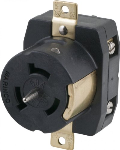
I think part of the confusion here, and it is indeed confusing, is that there are different plug/receptacles for 50A 120/240V (most common), and 50A 120V (increasingly uncommon). Both are barrel plugs with 3 prongs, but the pin arrangement is different and you can't plug one into the other.


The 120/240V plug has pins for L1, L2, and N. Ground is via the plug body. Two of the 3 pins have bends that angle outward.


The 120V plug has pins for L, N, and G. The plug body is also G.


The key difference is that the 120V plug only carries one L.


Here are some diagrams of the plugs that should help. I'm not sure if these are plug or receptacle diagrams, so be careful about exact pin assignments.
 

Attachments

  • 50A120V.jpg
    50A120V.jpg
    27.8 KB · Views: 58
  • 50A120:240V.jpg
    50A120:240V.jpg
    29.2 KB · Views: 58
Last edited:
This seams more complicated than I would think. I want to understand and you members know more than I!

I read about in and out of phase. Someone mentioned that the 2 lines must be out of phase. If there out of phase I would think as one line goes POS the other is going NEG. Yes? Which would mean a short I would think?
 
Does it look like this? The fourth is on the outer edge is the ground. Set up so either a 125 OR a 250 male plug can use same outlet.
View attachment 133976


That's where this skips the rails. What you show is a 50A 120/240V receptacle. You can NOT plug a 50A 120V plug or cord into a 120/240V receptacle, and vice versa. The pin keying if different.
 
This seams more complicated than I would think. I want to understand and you members know more than I!

I read about in and out of phase. Someone mentioned that the 2 lines must be out of phase. If there out of phase I would think as one line goes POS the other is going NEG. Yes? Which would mean a short I would think?
Nope! And nobody is suggesting connecting the 2 points only measuring the V between them... no difference than measuring between hot and neutral on 120V AC circuit.
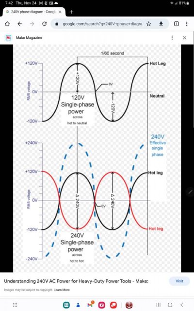
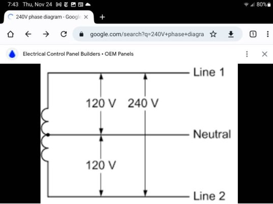
These diagrams might help.
The 240V power cord is really a 4 wire cord and the receptacles have 4 contacts (not 4 as some have indicated) the 4th... a ground is separate from the neutral. On 240V twist locks the ground is on the OD of the recepticle and ID of the plug.Screenshot_20221124_074214_Chrome.jpgScreenshot_20221124_074312_Chrome.jpg
 
Last edited:
This seams more complicated than I would think. I want to understand and you members know more than I!

I read about in and out of phase. Someone mentioned that the 2 lines must be out of phase. If there out of phase I would think as one line goes POS the other is going NEG. Yes? Which would mean a short I would think?

Not a short as they are going though a load "usually". Like a 240V dryer element that is a resistor that doesn't "short" but transforms the energy to a hot wire (heat). Please help from those that can explain it better.

This is where I mentioned that I know electrical "copycatting" or "building" but not theory well enough to be a certified electrician or instructor.
 
Okay, a little more info. The 50 amp pedestals in the marina are three conductor plugs. One neutral/ground, and two 115v hots, measured with a multimeter. Across the two hots is 230v measured.


OK, this wasn't part of the info LeoKa offered up. Are you in the same marina and is this your info? Just trying to get the info straight, and thinking about psneeld reasons for not participating in these conversations since the info is often unclear and incomplete.


At the last slip,LeoKa was plugged into a 50 amp pedestal, labeled "50amp 125/250v"
He was using an adapter which used three conductors, the TO three conductors, but was labeled 50amp 125v at the end that plugged into the pedestal, and 50 amp 125v at the other end. The three conductors were neutral/ground, and 125v, 125v, but measuring across the two 125v conductors yielded O volts, so apparently the two conductors are of the same phase, with one of the 125v wires terminating within the adapter pigtail. So we extrapolate that the boat is wired 50 amp, 125v ONLY.
The above info is confirmed by testing.


Again, new info, so thanks. I'm guessing he was using the 50A 120/240V male to 50A 120V female adapter that he listed early on. This makes sense, however I think you measurements are being misinterpreted, probably because the 120/240V and 120V pinouts are different. The pins are L, N, G on the 120V plug. On the 120/240V end they are L1, L1, N. Measuring can look like two lines, but it's actually a N & G.


Now for the extrapolation. . . . I would THINK (but would have to be verified by testing) that the outputs from two adjacent pedestals would be of the same phase


Definitely NOT a safe assumption. In fact, they are often intentionally on different phases to spread out the loads.


. . . . but they may NOT be, (again, must test) if they ARE, then using a reverse adapter at the boat end, it should be possible to plug in two extension cords to the two male inputs of the reverse adapter on the boat, and being of the same phase, it should provide the same 125v, but at 60 amps to the boat (limited to 50 amps by the panel circuit breaker on the boat). If they are of opposing phases, it obviously won't work.

With me so far? Any holes in our thinking? Seriously, if we're misinterpreting this, please chime in here!

Electrically you can do this, and it's what the bootleg ParkWorld adapter does. But doing so is potentially very dangerous. No offense intended, but you guys have demonstrated that you should not be messing with such stuff. What you are contemplating, which is paralleling two independent power circuits, violates every electric code, every building code, every boat wiring standard, and is just a horrific electric practice. I can think of only a small handful of people on this forum who know enough to safely do such a thing, but none of them would ever do it because it's so totally wrong. All it takes is someone inadvertently moving one of your plugs to another outlet to create a dead short. Or to unplug one end and touch a prong and get electrocuted. Or an electrician who turns off power to a pedestal to work on it, only to find that it's still live and he's now dead because you are backfeeding it through your adapters. DO NOT DO IT. I don't know how to be more emphatic about this. This is what kills people, burns down marinas, and does other socially unacceptable things.
 
Nope! And nobody is suggesting connecting the 2 points only measuring the V between them... no difference than measuring between hot and neutral on 120V AC circuit.
These diagrams might help.
The 240V power cord is really a 4 wire cord and the receptacles have 4 contacts (not 4 as some have indicated) the 4th... a ground is separate from the neutral. On 240V twist locks the ground is on the OD of the recepticle and ID of the plug.View attachment 133981View attachment 133982

Thanks! The lower pic I fully understand. It gets a little confusing with 3 phase.
 
Perhaps if the OP would post pictures of cable ends , cable adapters and pedestal, then there would be less speculation. It has become apparent that the written explanation is being interpreted in multiple ways resulting in different suggestions.
 
The minute Leoka discovered that neither Marinco nor Hubbell made such an adapter it should haven been obvious this wasn’t the correct direction.
 

Latest posts

Back
Top Bottom