240/120v switch

The friendliest place on the web for anyone who enjoys boating.
If you have answers, please help by responding to the unanswered posts.

chasles22

Veteran Member
Joined
Jun 24, 2022
Messages
26
Vessel Name
Cavalier
Vessel Make
Cheoy Lee LRC 61'
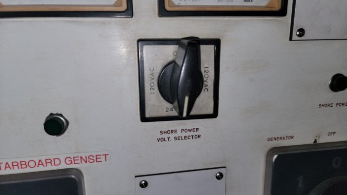
Howdy. I bought a boat, my first big'un. I'm trying to unwind how the electrical system works. Consider me smarter than the average bear when it comes to electronics and electrical systems... Yet I'm befuddled. What does the switch in the attachment do? Some info/assumptions...

The boat takes a single 50a shore power to run everything

The boat has 2 generators each 15kw which can only be connected to the boat one at a time (not paralleled.

When I turn the switch to 240 (on the hard in the boat yard) it shows appx 210v (assuming they have 3 phase power and this is accurate). When I turn it to 120v it shows appx 120v.

So what the heck does this thing do? Is this just a Europe 240v on a single line switch so in North America it should always be on 120v?

The issue is that previous owner had it on 110v and everything was working fine on shore power. Then we pulled out to take it to yard and air conditioning wouldn't work on generator (kept popping dual pole breaker). Just a point of fact. Then in the yard the batteries started to drain and weren't charging even with shore power. A yard guy change the switch to 240v.... No one seems to know why.
 

Attachments

  • 20220815_144800.jpg
    20220815_144800.jpg
    61 KB · Views: 49
Really going to need more info.... that 50a cord is a 240v cord, L1, L2, N, G. This is single phase, but yes if the marina is fed from 3-phase, you would see 208v between 1 and 2, but thats another topic.
I dont understand what that switch is doing, or why you would seperate the legs. But it would appear some circuits are on l1, some on l2, and if you select only 1, the others dont get powered. But why it would be set up that way i do not understand with the info provided.
 
Often labels for switches like tjat on boats can be confusing, often not really describing really what is happening with the power..

Could be piwer fowm different power inlets on opposite sides the boat, who knowd....

As already posted, need lots more info about the whole system.

Often because of huge variations the way boats are wirred, internet discussions on systems arehit or miss for accuracy
 
IMO
You don't mention any details of your boat... mfg, year, model, etc nor the type(s) of shore power inlets present?

Speculation by others probably not going to be helpful unless you find someone with an identical set up (assuming that is your hope).

Best approach is to dig in and do the tracing and documenting a schematic of inputs & outputs for that switch to really understand what you have. If you are savy w electrical its not highly technical just a fair amount of work to go through it systematically and document as you go. There are some tools, meters, test leads w clips, tone tracers, etc that can help.

Bottom line spe ulation might give you some possibilities but only you (or a hired hand) will know for sure. Also IMO the effort will be worth it and you will benefit from the effort and knowledge.
 
This is only a guess.

Everything on my boat is 120 VAC, but I have 50 amp 240 VAC inlet. When I go to to the boatyard, I can only get 20 amp 120 VAC. So I have a dog bone (short adapter cord) that goes in the boat inlet and has a normal house receptacle plug on the other end. Besides converting the plug, it also ties the 2 hot legs together, so that everything potentially has power. Obviously the limitation is the boatyard's receptacle circuit breaker.

Maybe this is what your switch does. Any appliance that's 240 VAC wouldn't work and might pop a circuit breaker. Wondering if your battery charger and air conditioning are 240 volt.

Ted
 
Does the boat have an isolation transformer? One possibility is that it's set up to accept either 240V/50A or 120V/30A shore power, and the selector switch tells it which to use.


Are there multiple shore power inlets, and are they all 120/240V/50A or are one or ore different and perhaps for 120V? Is there another selector switch somewhere to select which inlet to use?


Can you post some picture of your whole electrical panel? Is we can see the other controls we might be able to narrow down what that selector might be.
 
Have you talked with the previous owner about this question? When you surveyed the vessel was everything "electrical" working properly? I've a friend who toasted all sorts of on board equipment as he struggled with a similar scenario so go easy.
 
thanks for the various comments. here are some more general thoughts.

sorry for the possible red herring on generator not running AC, probably unrelated.

the boat is a 1977 cheoy lee 61 LRC. it's old enough and unique enough that hoping someone has the same scenario is... hopeless. i was just hoping someone might have some good general thoughts on what this switch generally does. i like the thought that it lets me pick one side of the 50z/240v 120v to use. that actually might help explain the AC tripping thing as well.

as far as i can tell there is only a single 50A shore power inlet. there are half a dozen 240v breakers (AC1, AC2, AC Pump, stove, dryer etc) and the rest of the AC breakers are split into "inverter 1" and "inverter 2" which i believe is a more modern labeling. there are two colors of 120V AC breakers (first 1/3 are black and pencil labeled as inverter 1, and 2/3 are red and pencil labeled as inverter 2).

lot's more to come on this. and i will post more pictures of the full panel, plus i won't be in the dark in the hot on the hard and i will have my trusty fluke meter so i will be more brave with tracing the path through the switch etc.

please keep any additional thoughts coming.
 
Can't say for certain on your panel, but on my panel the red / orange ringed breakers are on a transfer switch and can be run from the inverter. Black ones are only shore power and generator.

16606629518148188273643779977414.jpg

Ted
 
Can't say for certain on your panel, but on my panel the red / orange ringed breakers are on a transfer switch and can be run from the inverter. Black ones are only shore power and generator.

Ted

thanks, interesting. i have basically the same, but as i mentioned they have no been labeled to correspond as inverter 1 and 2... wonder if they were previously like that and in 2015 when they added new generators and second inverter they just followed that logic to make it inverter 1 and 2.
 
Just going to add I do work with places that have 3 phase 120/240 in the states funny enough had 2 different places back to back and the generator was set wrong to line. Only way to verify is at the pedestal and a meter.

Now what does the switch do? Long guess to me without seeing how it is wired.
 
Switches voltmeter connections:
120V Line 1 to N
240V Line 1 to Line 2
120V Line 2 to N

The labeling could be more clear
 
Genius. This is almost entirely it. I was staring at the wiring this morning this is probably correct. I'll stab it with a fluke tomorrow and see if that makes sense with how it's wired...
 
Yup. After digging in with my (finally aboard tools and trustworthy fluke meter) I can confirm that this is a dumbly labeled switch. It indeed selects what the voltmeter shows and that's it.
 

Latest posts

Back
Top Bottom