jwag956
Veteran Member
On our new-to-us 1990 GB 42 the survey called out a non-functioning amp hour meter - turns out that's because the shunt actually melted (hmm).
Ideally, we'd like to find an exact replacement - 2nd best is a newer 'compatible' shunt and of course last resort is to replace the gauge and shunt
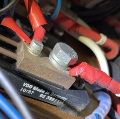
The main part of the shunt has the inscription:
VDO Made in Germany
10/87 03 330/114
The brass terminal connector says:
108 6mV 80A
I can't tell if that's 108.6 mV (that seems odd) or 6mV? And what does 108 mean?
Does anyone know the actual spec for this shunt?
Thanks!
Ideally, we'd like to find an exact replacement - 2nd best is a newer 'compatible' shunt and of course last resort is to replace the gauge and shunt
The main part of the shunt has the inscription:
VDO Made in Germany
10/87 03 330/114
The brass terminal connector says:
108 6mV 80A
I can't tell if that's 108.6 mV (that seems odd) or 6mV? And what does 108 mean?
Does anyone know the actual spec for this shunt?
Thanks!