RPM gauge

The friendliest place on the web for anyone who enjoys boating.
If you have answers, please help by responding to the unanswered posts.

captbuddy

Veteran Member
Joined
May 28, 2016
Messages
81
Location
United States
Vessel Make
1978 Prairie 29ft.
Can someone tell me why would my rpm gaugestart jumping up and down unless I get over 3000 rpm. It doesn't work while you are at idle. About half trolle it starts jumping all over. Do I just need to replace the gsuge.
 
Very likely a wiring problem. Check every connection and the condition of the grounds.
Many diesels use a tap from the alternator for the tach signal so check there.
 
Last edited:
Yeah, put a ac voltmeter on the alternator W terminal. More indirectly, a dc voltmeter on the D+ terminal to help analyze.
 
Rpm gauge

Dave. Thanks for the info. Without knowing much about alternator but I did check to see if I had any loose connections. Found none. How do I ck with my volt meter. I mean with positive and negative leads. Where to put them. Thanks in advance.
 
Diesel engine?

If so, is there a tach drive generator?

If diesel, and no generator/sensor, then very likely a wire on the alternator.

How many alternator wires or studs are present? A pix of the back of the alternator would be good to view. Any marks?
 
Rpm gauge

I'm trying to download the picture I took. Obviously don't know how. Will keep trying.
 

Attachments

  • 20220513_200647.jpg
    20220513_200647.jpg
    197.4 KB · Views: 43
What engine?
Not all engines use the alt as a source for the Tach
On those thatvdo I believe it's one of the smaller wires likely with a plug terminal. Check for any corrosion, clean, lube & replace.

My Yanmar has a sensor that picks up a signal from the flywheel and has 2 leads from it. With this arrangement there are a couple causes if intermittent signal and tach jumping or not responding at all.
Wire terminals that slip onto the sensor- corrosion, clean then grease
Sensor adjustment / cleanliness - position / proximity to flywheel is important as well as being clean. Careful if removing to know where it is screw it is gently to get contact and count the revs. Then back it all the way out and clean. Replace to get contact and back it out the same # turns.
 
You appear to have a Delco “one wire” alternator. Does not have a tach signal.
There must be a different signal source.
 
It's a 1978 perkins 1-408 diesel. Found a site that says prior to 1980 they didn't use alternator but suppose to be a round plate 3" after of alternator bracket on starboard side of engine. This supposed to have a gear in it. Mine does not have any plate on starboard side.
 
Perk 1978 4108 shop manual lists #41 as Tach Drive
 

Attachments

  • Perk 4108.jpg
    Perk 4108.jpg
    186.4 KB · Views: 30
Thanks Bacchus
No problem. I know next to nothing about the engine but a quick search turned up the manual. I scanned the pages referenced in the index for tach but couldn't find a sensor / sending unit. Maybe a more thorough dig would find something.
View attachment 128649
 
Last edited:
Everywhere the books states the location of my tach sending unit is supposed to be, it is not. I did read that the perkins engine was built all over the world so they would not all be the same. I found this sending unit on the port side. In the manual it says provision is made, on the right side of engine, for a drive at half engine speed to be taken from the oil pump spiral gear to a tach.
 

Attachments

  • 20220515_125133.jpg
    20220515_125133.jpg
    167.5 KB · Views: 17
Everywhere the books states the location of my tach sending unit is supposed to be, it is not. I did read that the perkins engine was built all over the world so they would not all be the same. I found this sending unit on the port side. In the manual it says provision is made, on the right side of engine, for a drive at half engine speed to be taken from the oil pump spiral gear to a tach.
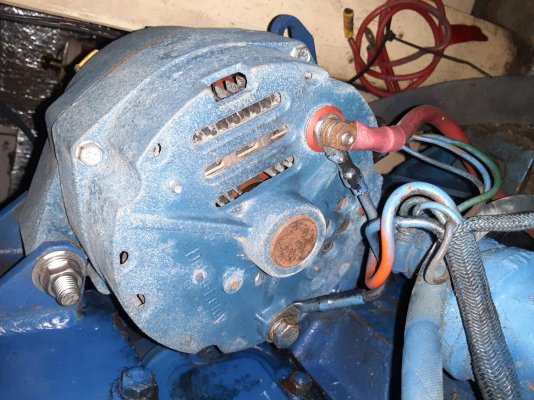
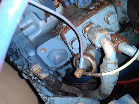
That looks like a pressure or temperature sending unit.
It may be time to trace the wires back from the tach to the engine.
 
It's not a tach drive.
 
Knot yet, that's not a good option. The wires go down from the flybridge through the wall in the head and then to the engine room. Was hoping someone on here new where to look. Thanks a bunch
 
You don't have to physically touch or see the complete wire length. After confirming the wire color at the helm tach headed to the engine follow as far as possible to make sure there isn't a connector at / near the helm.
If a bundle is head towards the ER start looking for wire bundles in ER headed to the engine. You may need to separate a bundle to search for that wire color. Colors should not change in the middle of a run especially if hidden. More often, if wire color changes it will be at a connector which should be more visible. Actually checking at connectors is a perfect place. If you find the colored wire on the helm side of the connector check yhe position to note the color that that position is mated to. If same fine, but if not start following / looking for the new wire color along the new cable run... another connector may enter the picture.
I've been successful with the above procedure when tracking small alternator wires to the helm... and I did find some color changes at connectors.
 
Last edited:
Don, I hate acting so stupid but which wire do I need to trace
 

Attachments

  • 20220516_162351.jpg
    20220516_162351.jpg
    132.9 KB · Views: 27
  • 20220516_161950.jpg
    20220516_161950.jpg
    106.8 KB · Views: 26
Don, I hate acting so stupid but which wire do I need to trace

1 or 2 of those wires are probably for lighting and should marry with others nearby.
Of the remaining wires, 1 or 2 may also connect to busses for the ground or positive.
That leaves the signal that should remain separate and head toward the engine room.

After reading Diver Dave's next post, I like the gray wire now.
 
Last edited:
Light gray has “S” penciled near. White has “lite” penciled near.
Betting S means sender.
Violet is marked “+” so that is consistent with that convention of switched ignition line.
I would consider putting a voltmeter on the S stud vs ground and see whats there. Guessing that it would be an ac voltage, and frequency increases with rpm.
 
Last edited:
Don, the white wire goes to light switch. The two purple wires goes to, one to oil pressure gauge and other goes to temp gauge. When looking at back of tach, the stud on the left there is a 10 awg wire that goes in the bundle heading to engine room. Could that be my culprit?
 
Yes
Explore those markings both molded in and penciled.
One looks like "GRND" and can't read the one on lower right... SEND.??
Common wires likely lighting and could be confirmed by turning on Nav lights and checking studs before & after w DVM. Those should be relatively easy to trace. Any heading to ER are the ones to trace further.
 
Last edited:
Don, I think I found it. I overlooked the s on gray wire. Traced it to junction. It went in next to black. Two brown wires came out other side. Found brown wire going into sensor on to of engine. Checked with ohms meter. One brown at connection I get a reading 17 to 18. Just keeps jumping. Other brown shows small number then goes to 0. Could I have found it
 

Attachments

  • 20220516_180209.jpg
    20220516_180209.jpg
    138.7 KB · Views: 15
  • 20220516_180231.jpg
    20220516_180231.jpg
    123 KB · Views: 13
Don. I went back in and loosened the nut to read the pressed in word on the gray wire. It says send.
 
I'm not the best on what signal should/ shouldn't be... maybe others can add something.
I guess I'd start by checking readings at the sensor and see if it continues through the plug or not. It may be more expediant to replace the sending unit as I doubt they are all that expensive. Not my favorite or best practice to just throw parts at it but it sometimes works.
You might find some knowledge / resource on BoatDiesel.com or via detailed search to figure out the correct sending unit output.
 
Can you run a temporary new wire directly from the engine sending unit to the tach via an open hatch or some other more direct path as a test?
If tach works the sender is OK and wiring is the culprit.
If tach doesn't work sender or tach is the area to work on.

I'm confused by the photo... when I zoom in on that send post I see a wire that is joined to a short jumper at the crimp terminal but the jumper goes to the same post?? Doesn't make sense?
 
Don, will try the jumper this afternoon and let you know. Not sure about the little wire you are talking about. Will look again when I get back. Thanks for all your help.
 
Don, that small black wire is connected to another black wire that goes over to the volt meter. Don't understand the shorter of the two going back to the same stud on rpm.
 

Latest posts

Back
Top Bottom