Problems changing Kohler 13.5CCOZ output from 120 to 240

The friendliest place on the web for anyone who enjoys boating.
If you have answers, please help by responding to the unanswered posts.
Joined
Sep 25, 2018
Messages
542
Location
USA
Vessel Name
Aruna
Vessel Make
Kristen Yachts 50 Pilot House
I have a Kohler 11CCFOZ/13.5CCOZ marine generator that I am struggling with changing from 120v to 240v. The reason I say 11CCFOZ/13.5CCOZ is that the generator was mis-labeled when the boat was built (according to the previous owner) - the 11CCFOZ is a 50hz unit, and the 13.5CCOZ is 60hz. At some point the unit was "converted" to 60hz since the boat has always been in the US and used on 60hz power. I mention this only in case there is some history or limitation with the 11CCFOZ, but I don't think there is.

The unit is currently producing 120v AC @ 60hz and can pump out close to 100 amps of power. It also has a three pole, with only one pole being used for the hot L1, 100 amp output breaker that looks original.

gen1.png

The specs say that this generator can output 120 or 240 volts, single phase. I'm trying to use it with a split phase set of inverters and need two different legs of 120v @ 60hz to each of them.

I have a neighbor with what appears to be the same exact generator that is already setup this way. I have confirmed the wiring on his matches the wiring I switched mine to.
gen2.jpg

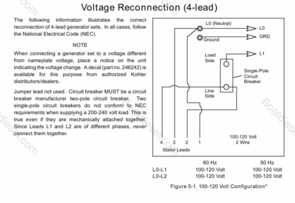
From the Installation and Operations manual, this is how the voltage connections are right now to produce 120v AC (picture above).
gen3.png

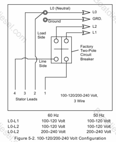
I have tried wiring it up like the above diagram, also from the operations and installation manual. This should give me two separate legs of 120v, but it doesn't. Instead, I get a pulsing amount of voltage ranging from 60v-130v (or sometimes higher or lower) depending on how I adjust the voltage regulator.

I've followed the process to adjust the voltage regulator several times, and never seem to be able to stabilize the voltage on either leg. I can see the lights on the voltage regulator and on the control board pulsing as the voltage goes up and down.

IMG_6362.jpg

The unit has the Powerboost voltage regulator, board B-258296, and when I flip it back to 120v it works just fine (after a quick adjustment).

I'm trying to determine whether it is even possible to produce 240v out of this set. I would think it would be since most all generators I've ever set hands on use a similar setup where you can convert them between 50/60hz and 120/240 volts with wiring and some patience.

I'm at a loss as to why I can't do it with this model, and am beginning to think there is a board or component that limits this unit to 120v, or I am being super stupid and forgot to do something.
 
I dont know that generator. Saying that, i have seen gensets with two 120V windings. In parallel, you get 120V at 2x current. In series you get 240 at 1x current rating.

The fig 5-2 schematic looks flawed to me. You would get 240 from L1 to L2, not L0 to L2.
 
Last edited:
Do you have any 240v appliances on board? If not, is there a reason you couldn't run the inputs in parallel off the single 120v feed from the gen?

On my boat, there's no 240v stuff, so the generator is wired for straight 120v and the 2 panel legs just run in parallel on generator power (in my case the inverter sub panel is only on 1 leg). Doing it that way means I can use the full output of the generator (6.5kw / 54 amps in my case) distributed however I want rather than being limited to 27 amps per leg if I wired the gen for 120/240.
 
I dont know that generator. Saying that, i have seen gensets with two 120V windings. In parallel, you get 120V at 2x current. In series you get 240 at 1x current rating.

The fig 5-2 schematic looks flawed to me. You would get 240 from L1 to L2, not L0 to L2.

I believe this set has 2 windings, and they're combined right now which is why I am getting 120v. And yes, the diagram text is wrong, but the wiring isn't, well at least as far as I know :)

Do you have any 240v appliances on board? If not, is there a reason you couldn't run the inputs in parallel off the single 120v feed from the gen?

On my boat, there's no 240v stuff, so the generator is wired for straight 120v and the 2 panel legs just run in parallel on generator power (in my case the inverter sub panel is only on 1 leg). Doing it that way means I can use the full output of the generator (6.5kw / 54 amps in my case) distributed however I want rather than being limited to 27 amps per leg if I wired the gen for 120/240.

I do not have 240 stuff on board now, but I may in the future.

I have the generator and inverters in parallel now, which is fine when I am charging via generator where I can get around 80-85 amps continuous across the two inverters and for various things.

At the dock is where it sucks where I have to limit the amount of power I can pull from a 50 amp, 240v, two leg connection down to just 50 amps at 120 volts. The inverters I am using (Victron Quattro) cannot be wired to have one configuration for generator, and one for AC shore power, similar to other manufacturers.

I have a large LiFePO4 battery bank, and having both inverters able to charge at full capacity while connected to shore power would be nice.

I'm less worried about balancing the legs if I were to be using 240v split phase for generator/inverter/shore as it's pretty well balanced now.
 
Steve
I see two errors on Figure 5-2: as noted in Post #2 and also N and G are not bonded at the connection block as they should be.

So, two issues with the techman schematic give me pause and I would suggest the dreaded phone call to Kohler Tech Support.
 
Steve, I'd suggest checking to see where the voltage regulator sense wires are connected. It may be that once re-wired for split phase, the sens wires are now picking up at the wrong points.


Since it was running in a 120V config, I expect that the regulator senses and regulates based on 120V. In a split phase configuration, it will need to sense one of the two L-N halves. Using the diagram lingo, that would be L0-L1, or Lo-L2.
 
It's also possible that the diagram has other mistakes in it. In particular, the polarity of the two windings. Based on the 120V diagram, winding 1-2 is in phase with winding 3-4. The split phase diagram shows 1-2/3-4, but in that config I think the two windings are in phase rather than out of phase. I have a suspicion that the correct wiring should be 1-2/4-3.
 
I believe this set has 2 windings, and they're combined right now which is why I am getting 120v. And yes, the diagram text is wrong, but the wiring isn't, well at least as far as I know :)

Here's the diagram I have steve. See attached.
 

Attachments

  • IMG_3779.jpg
    IMG_3779.jpg
    139.4 KB · Views: 20
The text is corrected, showing L1-L2 as 240V


True. The diagram itself is the same though.

Ultimately I’ve reverted back to a single leg 120v, 100 amp setup for now. Kohler was very little help and I would rather not damage something experimenting.
 
True. The diagram itself is the same though.

Ultimately I’ve reverted back to a single leg 120v, 100 amp setup for now. Kohler was very little help and I would rather not damage something experimenting.

Yes, you certainly don’t want to let the smoke out of it…
 
At the dock is where it sucks where I have to limit the amount of power I can pull from a 50 amp, 240v, two leg connection down to just 50 amps at 120 volts. The inverters I am using (Victron Quattro) cannot be wired to have one configuration for generator, and one for AC shore power, similar to other manufacturers.

If you have 50A240v in AND you have only 120v loads, there is no difference. Connect L1 and L2 to your gen output. If you are using a break before you make switch to change from gen to shore power you are fine. When on gen, L1 and L2 will be in synch, but who cares. 1 inverter and some other loads wired L1, 2nd inverter and different loads wired for L2. They will all work no matter if on shore or gen.

If you rewire the gen for 240v you have to balance the loads of l1 and l2 for it to run most efficiently. If you run them together as mentioned the load will always naturally split between the winding and ballance. Until such time you need 240v for an appliance, you are better to leave it as wired and wire to the panel as described.
 
I suspect the voltage regulator sense connections are wrong for 120/240. And, is this a digital control unit? If so there is a menu setting for output configuration.
 
This is all single-phase. No chance of getting anything out of phase.
 
This is all single-phase. No chance of getting anything out of phase.


Transformers and generator systems can have separate windings, where winding phasing is of extreme importance. 3 phase or single phase.
 
Transformers and generator systems can have separate windings, where winding phasing is of extreme importance. 3 phase or single phase.


I don't follow. A single-phase transformer or generator is just that.
 
https://www.electronics-tutorials.ws/wp-content/uploads/2013/09/trans61.gif?fit=297,190

Shown is a single phase transformer. The dots indicate “phasing”. In this context, it means the polarity of the voltages, with a given core flux. So, all the dotted windings will have a rising voltage (positive current) at the same time.
The non-dotted windings will have a falling voltage (negative current) at that time. Of course, current only when loaded.
 
Last edited:
https://www.electronics-tutorials.ws/wp-content/uploads/2013/09/trans61.gif?fit=297%2C190

Shown is a single phase transformer. The dots indicate “phasing”. In this context, it means the polarity of the voltages, with a given core flux. So, all the dotted windings will have a rising voltage (positive current) at the same time.
The non-dotted windings will have a falling voltage (negative current) at that time. Of course, current only when loaded.


OK, now I know what you mean. I think that is polarity, not phasing.
 
Yep, terminology is confusing. Polarity might be confusing too on ac circuits [emoji16]
 
I have a Kohler 11CCFOZ/13.5CCOZ marine generator that I am struggling with changing from 120v to 240v. The reason I say 11CCFOZ/13.5CCOZ is that the generator was mis-labeled when the boat was built (according to the previous owner) - the 11CCFOZ is a 50hz unit, and the 13.5CCOZ is 60hz. At some point the unit was "converted" to 60hz since the boat has always been in the US and used on 60hz power. I mention this only in case there is some history or limitation with the 11CCFOZ, but I don't think there is.

The unit is currently producing 120v AC @ 60hz and can pump out close to 100 amps of power. It also has a three pole, with only one pole being used for the hot L1, 100 amp output breaker that looks original.

View attachment 127952

The specs say that this generator can output 120 or 240 volts, single phase. I'm trying to use it with a split phase set of inverters and need two different legs of 120v @ 60hz to each of them.

I have a neighbor with what appears to be the same exact generator that is already setup this way. I have confirmed the wiring on his matches the wiring I switched mine to.

View attachment 127953

From the Installation and Operations manual, this is how the voltage connections are right now to produce 120v AC (picture above).

View attachment 127954

I have tried wiring it up like the above diagram, also from the operations and installation manual. This should give me two separate legs of 120v, but it doesn't. Instead, I get a pulsing amount of voltage ranging from 60v-130v (or sometimes higher or lower) depending on how I adjust the voltage regulator.

I've followed the process to adjust the voltage regulator several times, and never seem to be able to stabilize the voltage on either leg. I can see the lights on the voltage regulator and on the control board pulsing as the voltage goes up and down.

View attachment 127955

The unit has the Powerboost voltage regulator, board B-258296, and when I flip it back to 120v it works just fine (after a quick adjustment).

I'm trying to determine whether it is even possible to produce 240v out of this set. I would think it would be since most all generators I've ever set hands on use a similar setup where you can convert them between 50/60hz and 120/240 volts with wiring and some patience.

I'm at a loss as to why I can't do it with this model, and am beginning to think there is a board or component that limits this unit to 120v, or I am being super stupid and forgot to do something.
There seems to be an error in Fig 5-2. I believe that L0-L1 gives 120VAC. L0-L2 gives 120VAC. You will get 240VAC with L1-L2, not L0-L2 as the Fig5-2 states. Just something to verify.
 
I have a Kohler 11CCFOZ/13.5CCOZ marine generator that I am struggling with changing from 120v to 240v. The reason I say 11CCFOZ/13.5CCOZ is that the generator was mis-labeled when the boat was built (according to the previous owner) - the 11CCFOZ is a 50hz unit, and the 13.5CCOZ is 60hz. At some point the unit was "converted" to 60hz since the boat has always been in the US and used on 60hz power. I mention this only in case there is some history or limitation with the 11CCFOZ, but I don't think there is.

The unit is currently producing 120v AC @ 60hz and can pump out close to 100 amps of power. It also has a three pole, with only one pole being used for the hot L1, 100 amp output breaker that looks original.

View attachment 127952

The specs say that this generator can output 120 or 240 volts, single phase. I'm trying to use it with a split phase set of inverters and need two different legs of 120v @ 60hz to each of them.

I have a neighbor with what appears to be the same exact generator that is already setup this way. I have confirmed the wiring on his matches the wiring I switched mine to.

View attachment 127953

From the Installation and Operations manual, this is how the voltage connections are right now to produce 120v AC (picture above).

View attachment 127954

I have tried wiring it up like the above diagram, also from the operations and installation manual. This should give me two separate legs of 120v, but it doesn't. Instead, I get a pulsing amount of voltage ranging from 60v-130v (or sometimes higher or lower) depending on how I adjust the voltage regulator.

I've followed the process to adjust the voltage regulator several times, and never seem to be able to stabilize the voltage on either leg. I can see the lights on the voltage regulator and on the control board pulsing as the voltage goes up and down.

View attachment 127955

The unit has the Powerboost voltage regulator, board B-258296, and when I flip it back to 120v it works just fine (after a quick adjustment).

I'm trying to determine whether it is even possible to produce 240v out of this set. I would think it would be since most all generators I've ever set hands on use a similar setup where you can convert them between 50/60hz and 120/240 volts with wiring and some patience.

I'm at a loss as to why I can't do it with this model, and am beginning to think there is a board or component that limits this unit to 120v, or I am being super stupid and forgot to do something.

https://www.colburnpower.com/mwdownloads/download/link/id/116/

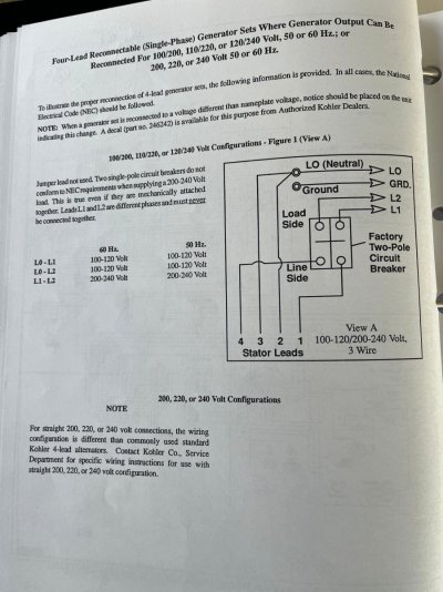
This should be your regulator
Trace v7 and v8 sense wires
In this diagram it is set for 240v
V7 and V8 are sensing 240 volt from 1 and 4 stator leads

If when it was wired for 120 v7 and v8 may be on neutral and the L1
One wire may need to be moved
 

Latest posts

Back
Top Bottom