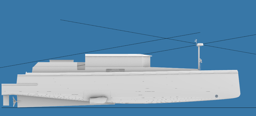
As the LM65h is designed to cruise at relative high speeds, close to its hull speed, there's - with traditional water displacement designs - a design challenge we needed to overcome. As a water displacement design encroaches hull speed, resistance goes up and efficiency is lost. That's not what we want, as she still needs a range to cross oceans ...
The efficiency losses at higher speeds are the result from the ship - as it creates its own bow wave - climbing up that wave, pushing - by rotational forces - the much wider stern under water. The results? Much higher drag, reduced efficiency, loss of range, or a lower cruising speed.
In order to counter the huge rise of drag resistance at high cruising speeds, we need to counter the rotational movement that pushes the stern deeper in the water. A trim wedge is added to the ship's stern design. The idea? As the ship speeds up and starts to rotate, the wedge helps push the aft ship out of the water, thus countering drag by reducing this rotational movement. I wanted a simple construction without moving parts, so a trim wedge, integrated in the aft underwater hull design, was the best solution.
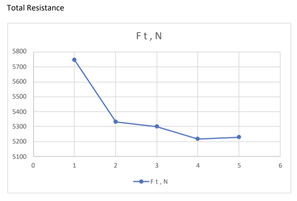
The NA thought he'd figured out the right sizes and angles, but we both felt that CFD (computational fluid dynamics) could help out in selecting the best trim wedge design. To that effect, we designed five different trim wedges and used CFD to establish the effects on the rotational movement, overall resistance, etc. The goal was to find the optimal solution between a lower hull resistance at speed, taking into account that a trim wedge by nature uses resistance to counter the ship's rotational movement.
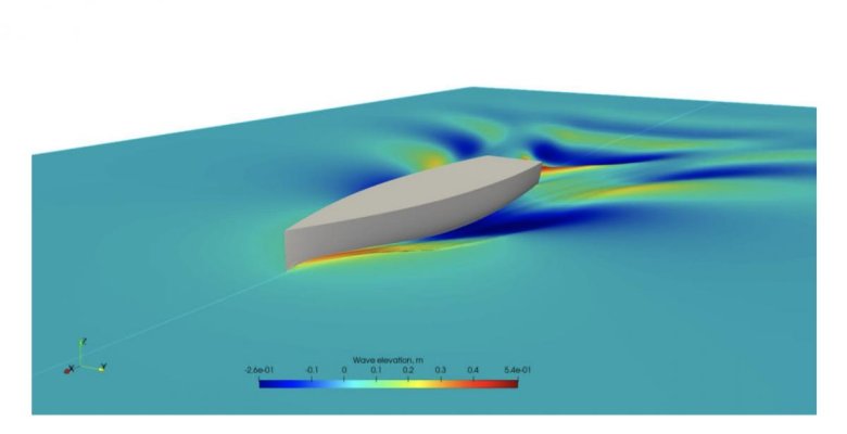
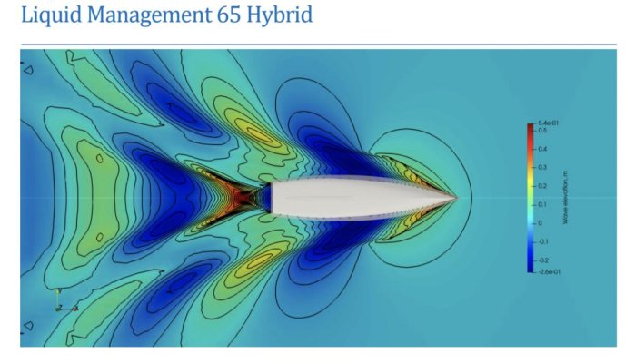
We made five cases / calculated through five designs. Here are some pics of the outcomes. A bow view of the hull slicing through the water at 10 knots, the associated wave field it creates, and the comparison of the five design cases. Nr. 4, as originally proposed by the NA, was the winner. Relative to no trim wedge, the optimized trim wedge design results in a 10% efficiency gain at 10 knots cruising speed.
Regards, Edwin & Veronika.
")