Isolation Transformer Help

The friendliest place on the web for anyone who enjoys boating.
If you have answers, please help by responding to the unanswered posts.
If all else fails, turn the inverter off. I mean completely off - cut the 12v off. Good luck.
 
So i guess only way to test the white wire is to run my shore power cable plug end into engine room next to transformer and do continuity test on ground terminal on cable to see if its also the white incoming wire?
 
do you have a volt/ohm meter on hand? it would be good to verify there's no connection between that ground terminal and the case. it looks isolated judging by the pictures, but an ohm reading would give the full picture.
regarding the incoming white wire, you absolutely need to see if it's attached to the shore inlet ground terminal and nowhere else.
if it is indeed the inlet ground it needs to hook to the transformer ground connection you just posted the picture of.
an ohm reading will tell if it's the inlet ground.
check that green attached to the case down low too. see where it goes.
 
So i guess only way to test the white wire is to run my shore power cable plug end into engine room next to transformer and do continuity test on ground terminal on cable to see if its also the white incoming wire?

yes, do that. while your doing that also check to make sure the inlet ground is not hooked to the transformer case, or anything else.
 
Just did continuity test on shore power cable, the ground lead on plug is in fact the white wire incoming.

Also did continuity test on the Green wire, it seems to ring meter on transformer case, mounting hardware, and even on the members holding transformer in place.
 
Guessing after rereading post, sounds like I need to disconnect green wire from ground stud, which I think green wire is what is causing ground to flow elsewhere.
 
Unhooked the green wire all together. With white wire only attached to Ground stud, everything still rings continuity no matter where I touch on the boat, case, mounting brackets, engine room door hinges, etc.
 
Unhooked the green wire all together. With white wire only attached to Ground stud, everything still rings continuity no matter where I touch on the boat, case, mounting brackets, engine room door hinges, etc.

unhook everything from the ground stud and re-check. ground stud should be isolated. at least that's what the drawing shows.
if the (isolated) white shows connection to the boat you need to follow it and see where it lands and disconnect it. did you look at the green wire attached to the transformer case down low?
it might be time for some professional help onboard. we can only do so much remotely.
 
Yes, I checked ground stud all by its self, nothing. Then hooked back up green wire without the white incoming wire, still nothing. Tested white incoming wire all by its self not attached to anything, it rings continuity with anything metal on boat. White wire must be grounded somewhere on the boat, where I have no idea.


What happens if I just don't hook up white wire back to Iso Trans?

the white wire is hooked somewhere else on the boat. that's a problem. you must find that connection and break it.
one of the main reasons to have the isolation transformer is to cut the ground wire from bringing stray current onboard. there's been discussion regarding another type of transformer that leaves the shore ground disconnected at the shore inlet. this will solve the tripping problem you're having, and sever the stray current connection, but it's not the way i would solve the problem. you have all the pieces in place to hook it up according to abyc guidelines, i would strive to get it right. i'd look at the shore inlet selector wiring, it's the most likely place your white wire is hooked up wrong.
 
There are still a couple of contradictory things here that need to get sorted out.


Lets start at the transformer. The wiring diagrams are clear that the ground connection/stud is supposed to be an isolated, internal ground shield in the transformer. That would be fantastic and is exactly how it should be. Yet there is a small jumper wire from the stud to the transformer mounting bolt tying it to the case. That's wrong. Can you see if there is any other wire connected to the stud, perhaps on the back side? I think it should be leading into the guts of the transformer along with the other wires. This has been modified in some way, and with some intent, but really should be put back the way it's supposed to be. This is important because as an internal ground shield, it should be connected to the shore ground via the shore cables. But is wired now, it's a case ground and should be connected to the ship's ground.


Next is the white wired that's part of the incoming power cable. It's color says it's the shore neutral. But the way it's originally wired might indicate it's being used as a green wire ground. This needs to be sorted out.


With the white wire disconnected from the transformer, you said there is continuity from the white wire to the shore cable plug ground, right? Is there also continuity to the shore plug neutral? Or to any other ground point in the boat? If there is, then the white wire is not exclusively begin used as the shore ground. Most likely the shore-side neutral and ground are bonded somewhere on the boat. They shouldn't be. Or the shore cable ground is tied to the ships ground. It shouldn't be.


If the white wire is indeed isolated from the shore plug neutral, and the ship's ground, then it would appear to be used to bring the shore ground to the transformer. In this case wrap green tape around as much of that wire as possible to properly indicate it's use. Other than the color being wrong, the original wiring to the transformer ground stud would actually be correct. But only if it's an isolated ground wire that connects to nothing other than the shore plug ground and the transformer.


I also think that before using that white wire, you really need to dig into the shore cable selector switch. You have at least three wires coming from each shore cable (line 1, Line 2, and ground), and more likely 4 (line 1, Neutral, Line 2, and ground). You said you can see that the selector switch switches red and black (line 1 and line 2). But you still should confirm what happens to the neutrals if they exist in the shore cable, and the grounds. The only correct treatment of the grounds would be to join them, and bring them to the ground shield in the transformer. They should not be bonded to the ships ground, and they should not be bonded to any neutral.


Once all this is sorted out, we will then need to figure out where/how/if you have a proper ship-side ground to neutral bond. That might have been the intent of the green jumper that you removed.
 
Is the core "shield" an obvious connection point? Because the core and the metal case should not connect to the shield, only the SP green.
 
Found a Port & Starboard side junction boxes, here is what is actually coming in from dock. On Port side, there is a green wire but its taped off. On Starboard side only see 3 wires.

Port
20211213-174217.jpg


Starboard
20211213-174709.jpg
 
With the various good points and questions that have been made, keep in mind that any changes you make absent understanding the onboard wiring could end up creating issues for the Aluminum hull.
 
I'd check to see if the white wires are on the ground lug of the shore inlets. Also look to see if that terminal is isolated from the hull when it's mounted. Then find the selector switch to see how it's wired. If it's a rotary switch it may be confusing looking as there can be a lot of terminals on them depending on the model.
A lot of times people make mistakes merging the shore power and generator wiring. If everything comes together at that selector there's a good chance the problem is there.
You really might think about getting a professional to look at it if it looks complicated. It wouldn't take long if everything is opened up and you've done the groundwork of finding all the connections.


Agreed. And to Sunchaser's comment, you are seeing how much of a ripple effect there can be with this stuff. So many things depend on each other, and you have to know how each part has been done before you can figure out what's right or wrong somewhere else.
 
If your power inlets are metallic body they must be isolated from the hull. The ground wire from shore must connect only to the electrostatic shield in the transformer, or you will always trip the dockside ground fault protection which is being installed everywhere. This is an easily overlooked item that in fact defeats the function of the isolation transformer, besides causing the fault trip with new GFI service.
 
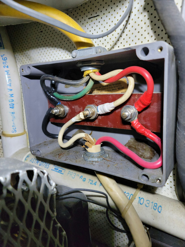
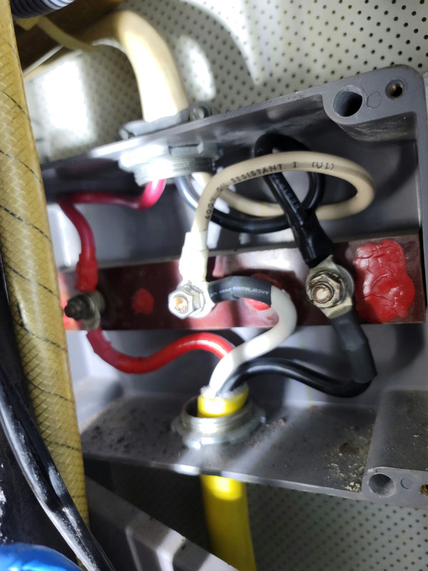
Pending confirmation that the two cables are input and output, here's what I think we are looking at:


1, 2, 3, 4 are the input side, and A, B, C, D are the output side.


Everything is wired correctly EXCEPT for the input neutral (white). It should not be connected to the ground lug, but instead should be disconnected and capped off.


It's also not clear whether the ground terminal is a chassis ground, or if it's an internal ground shield in the transformer. You could disconnect the wire that's internal to the transformer and meter it to see if it's isolated from the case or not. If it's isolated, then there are further problems. If it's a case ground then all is well, but there isn't an input-side ground shield which I suspect is common for older transformers. Note that the shore power ground is NOT brought to the transformer.

The shore power ground is/should be brought to the transformer, it must travel with energized conductors, it is connected to the shield between the primary and secondary windings (see attached diagram). Perhaps I'm misunderstanding what you said.

For a 240 VAC primary transformer, the inlet cable should consist of three wires, two hots (L1 and L2) and a safety ground. There is no neutral

Others have offered good advice, so I won't repeat any more of that, other than to say, the last thing you want to do with shore power wiring is guess about anything. Transformers, wired for polarization or isolation, are pretty simple devices, there are primary and secondary connections, and taps if they have boosting capability. That's it. Most transformers have a schematic diagram either on the outside of the case or inside the removable cover. See attached example. It's really important to get that schematic, from the manufacturer if necessary, before making any changes.
 

Attachments

  • 061419_784.jpg
    061419_784.jpg
    106.3 KB · Views: 18
  • 072811419.jpg
    072811419.jpg
    112.9 KB · Views: 20
  • Isolation Transformer Schematic 240.jpg
    Isolation Transformer Schematic 240.jpg
    124.5 KB · Views: 19
I’ve been quiet on this thread. As mentioned several times already, you need to see the whole picture. I have yet to see enough to understand why the transformer is wired the way it is. I haven’t seen enough to say it is wrong but what I have seen doesn’t look right. I am hoping by this point the OP has figured out he needs professional help. I don’t like venturing a guess, it’s too dangerous if you guess wrong. I will remain quiet until I feel I have the full picture.

It can be ver difficult to trace wires through a boat. I often hear “it is to difficult to follow or it disappears in a bulkhead”. The fact is there is no short cut. You either find a way to follow the wire or you disconnect it at both ends and preform a continuity test. You have to know!
 
We made it down to Jacksonville and boat will stay here for the time being, the electrical at this marina works great with our system, same as the marina we stayed at night before in Fernandina.

I have no problems getting professional help, however in the past, I have hired 2 different "Electrical Experts" one in Maryland, and other in Virginia to help with other non-related electrical questions that we had. Only to spend about $1K on each separate instance and got absolutely nothing fixed and no questions answered.

Am sure there are some great "Electrical Experts" out there in the world, but so far I have not been able to find them, nor was I impressed with the 2 I have hired so far. Think most Electricians, AC/Heater, and Mechanics are all pretty much part replacement people now, most lack the fundamental understanding how to read, diagnose & trouble shoot an issues.

Was told by new boat neighbor at Marina in Jacksonville that there is a good electrician at marina, so maybe I will try this again and see if I can get lucky.

You have already probably done this, but have you tested your SP cables (or swapped them out) to ensure they are ok? I would also test both the breakers and the inbound cables. One should work if the other doesn’t, but if they have some age on them, maybe not. I share your view that the ground connection is incorrect, based upon the standard set up for an isolation transformer, along with the image of the wiring document we looked at. I believe the white inbound is a grounding connection. The jumper should not be there, in my opinion. Hope the electrician is capable. Have you thought about finding the distributors of the isolator to see if they have electricians that know their products in Jacksonville?
 
We made it down to Jacksonville and boat will stay here for the time being, the electrical at this marina works great with our system, same as the marina we stayed at night before in Fernandina.

Was told by new boat neighbor at Marina in Jacksonville that there is a good electrician at marina, so maybe I will try this again and see if I can get lucky.


I didn't realize you were in transit on that route...

FWIW, on the previous boat we tripped the new GFCI breakers at Golden Isles (St. Simons Island) and Harborwalk (Georgetown) marinas.

Oddly (in my mind), we did NOT trip the new breakers at Fernandina Beach... and those were all newly installed just prior to our northbound passage in early 2020. I had been thinking that if we didnt trip those, we'd be fine everywhere. Au contraire.

Eric Weatherly, New Point Marine, did some good electrical work for us (new charger install) when we were at Ortega Landing over that winter. He does work for folks in several of the nearby marinas there...

-Chris
 
Ranger, that is too funny. We also had issues at Golden Isles (St. Simons Island), which is where I was stopped at when I started this thread.

We also had issues at Harborwalk (Georgetown), we just moved next door to Hazzard Marina and had no issues.

We also had issues at Isle of Palms on their new pedestals, so they moved us to a different section that had older pedestals, no problem on the hooking up however they only had 208v at this section. We can't run AC/Heat on 208v everything else no prob. So we moved down to Toler's Cove a little closer to Charleston, had zero issues there.

We are at Lamb's currently which is right next door to Ortega.
 
Once I twigged on that you had been en route down that way, I figured I could predict where at least some of your trouble spots could have been.

When we were going northbound in early 2018, Golden Isles still had the older pedestals, so we had no issues. Can't remember, on the way south in late 2019, but on the early 2020 return, no joy.

Harborwalk still has (had?) an area with older pedestals, so when we first encountered the problem on their new pedestals, probably our 2020 return, they just moved us to the inside of their older section.

I still have no clue why we didn't trip the new breakers at Fernandina Beach, though.

Anyway, since then we got a different boat, isolation transformer, had no issues anywhere on the way up from Ft. Myers... including Golden Isles and Harborwalk.

-Chris
 
We made it down to Jacksonville and boat will stay here for the time being, the electrical at this marina works great with our system, same as the marina we stayed at night before in Fernandina.

I have no problems getting professional help, however in the past, I have hired 2 different "Electrical Experts" one in Maryland, and other in Virginia to help with other non-related electrical questions that we had. Only to spend about $1K on each separate instance and got absolutely nothing fixed and no questions answered.

Am sure there are some great "Electrical Experts" out there in the world, but so far I have not been able to find them, nor was I impressed with the 2 I have hired so far. Think most Electricians, AC/Heater, and Mechanics are all pretty much part replacement people now, most lack the fundamental understanding how to read, diagnose & trouble shoot an issues.

Was told by new boat neighbor at Marina in Jacksonville that there is a good electrician at marina, so maybe I will try this again and see if I can get lucky.

I share your consternation regarding "experts", and the time and money that can be wasted, while they may be well-meaning, if they don't have the skills it's a shot in the dark.

You can avoid some of this issue for electrical work by only hiring technicians who have an ABYC Electrical Certification. You can search for them and confirm certs here https://abycinc.org/mpage/findatech

Any time you have electrical work done, it should be prefaced with, "everything you do must be ABYC compliant" and "if you make any changes or installations, I need a diagram to go with it".
 
Lambs has competent folks who can straighten that out for you. Just worked with them on an aluminum motor yacht that was leaking AC current above 30ma level. They straightened it out in short order.

Ranger, that is too funny. We also had issues at Golden Isles (St. Simons Island), which is where I was stopped at when I started this thread.

We also had issues at Harborwalk (Georgetown), we just moved next door to Hazzard Marina and had no issues.

We also had issues at Isle of Palms on their new pedestals, so they moved us to a different section that had older pedestals, no problem on the hooking up however they only had 208v at this section. We can't run AC/Heat on 208v everything else no prob. So we moved down to Toler's Cove a little closer to Charleston, had zero issues there.

We are at Lamb's currently which is right next door to Ortega.
 
If your power inlets are metallic body they must be isolated from the hull. The ground wire from shore must connect only to the electrostatic shield in the transformer, or you will always trip the dockside ground fault protection which is being installed everywhere. This is an easily overlooked item that in fact defeats the function of the isolation transformer, besides causing the fault trip with new GFI service.

Just to be sure this didn’t get overlooked. Shorepower inlets have a jumper preinstalled in them that transfers incoming shorepower ground to the metallic hull. If the jumpers have not been removed on both inlets on your boat, or if an inlet has been replaced and the jumper left intact, that needs to be the first thing rectified on a metal hull vessel with a transformer. I have found more than a dozen metal hulled vessels where this was not done.
 
I had trouble identifying the transformer's terminals as related to the schematic. I do have one comment however and that is in normal wiring, the ''white wire'' it the GROUNDED CONDUCTOR and is needed to be connected. The green wire is the GROUNDING CONDUCTOR and should not have current flowing in it other than in a fault condition.

The wires as related to the transformer's schematic should have primary voltage connected to terminals H1 and H2 OR H1 and H3.

Yes, secondaries X1, X2 & X3 can be connected to loads BUT X2 & X3 are transformer taps to vary the output voltage. You want the output to be connected to X1 and EITHER X2 or X3

I suggest the OP remove (tag first) the wiring from X1, X2 & X3 and of course REMOVE THE GREEN WIRE from any terminal other than from the shield terminal.

Next BE CAREFUL!!!! Connect the transformer to a pedestal for power and MEASURE the voltages on the terminal X1 in relationship to X2 and then from X1 to X3.

And note, the output voltage can further be varied by the transformer's primary connections such as selecting pair H1 &H2 0r H1 and H3.

AND BE VERY CAREFUL MAKING VOLTAGE MEASUREMENTS, HAVE SOMEONE WITH YOU in case of an accident. Good luck
 
Back
Top Bottom