Inverter tech

The friendliest place on the web for anyone who enjoys boating.
If you have answers, please help by responding to the unanswered posts.
Due to the shortage of employees and parts. I think it highly unlikely that you will be able to find anyone to work on it and if you do you will most likely find no parts available. Your best bet is probably to put it on ebay as is and hope some one else is desperately looking for parts and gladly buys your mistake.


Yes I might end up doing that.
 
You have to decide if it's cheaper to buy another, or pay to ship.


Marine Repair & Maintenance, On-Board Marine Services- Bellingham WA Is in Blaine, Wa. on the spit or Bellingham.

www.s3maritime.com authorized repair center for Xantrex in Seattle near Salmon Bay.


Xantrex Authorized Service Center 24/7 Repair | Mark Snyder Electric San Diego


Inverter Service Center Back east somewhere but a Xantrex dealer.
Inverter Repair Service - e Marine Systems Florida.


I took it to Salmon bay one. The tech said, he could not start it. That was it. I still had to pay.
 
Sounds like you put 120V into the DC side. This will for sure blow the input capacitors (they are probably only rated for 25V for a 12V inverter). Take a close look at the caps on the DC input side. Any bulging? Measure resistance on the DC input side. Probably shorted. Remove the caps. Still shorted? Then probably also the input FETs. The caps are easy to replace, so are the input FETs/transistors if you are handy with the soldering iron. Of course, there could be additional damage.


Yes I can handle soldering. Thanks for the help.
 
Here we go.

The inverter has an input section that transforms 12V to an intermediate DC level typically 160V and an output section that takes that DC and transforms it to AC. Your problem is likely in the input section.

The input section is around where your two transformers are. Check the capacitors in this area for bulging. We'll do some checks without desoldering anything. Measure the resistance of the caps on the board. There will be some parasitic resistance but they should not be shorted. If all the caps are good it is time to move to the transistors.

There should be a row of FETs/transistors with heatsinks close to the input side. Each has three pins. Two of them (source and drain) have good sized copper traces going to them (they carry a lot of current). The other pin is the gate. Check resistance between the gate and the other two. It should not be shorted. Check resistance between the source and drain. Again should not be shorted. Do this for all FETs in the input side. If you find some that have different resistance than the rest, they are likely faulty and need to be replaced.

Next to each gate there should be a resistor. Measure all of them. Pay attention to the ones next to any suspect transistor. A shorted transistor can burn out the gate resistor. If you know how to read the color coding, you can compare to your measured values.

At this point you should have identified damaged caps (possibly), shorted transistors (pretty much a given) and bad gate resistors (possibly).

Once you get that far, we can figure out how to identify proper replacements.
 
Last edited:
Here we go.

The inverter has an input part that transforms 12V to an intermediate DC level typically 160V and an output part that takes that DC and transforms it to AC. Your problem is likely in the input section.

The input section is around where your two transformers are. Check the capacitors in this area for bulging. We'll do some checks without desoldering anything. Measure the resistance of the caps on the board. There will be some parasitic resistance but they should not be shorted. If all the caps are good it is time to move to the transistors.

There should be a row of FETs/transistors with heatsinks close to the input side. Each has three pins. Two of them (source and drain) have good sized copper traces going to them (they carry a lot of current). The other pin is the gate. Check resistance between the gate and the other two. It should not be shorted. Check resistance between the source and drain. Again should not be shorted. Do this for all FETs in the input side. If you find some that have different resistance than the rest, they are likely faulty and need to be replaced.

Once you get that far, we can figure out how to identify a proper replacement.


Thank you so much. You guys are giving me great guidance. I will dive into this and maybe post some photos about the results. It might take a little for me to accomplish the one by one check, but I think it is worth it.
 
"there are scrappers that take electronics apart and put the guts on ebay, "

How does one locate electronics scrappers?

I replaced a TV that still works and would prefer to see it scrapped rather than crushed in a landfill.
 
Unfortunately, anything in the unit could be damaged with FOD. As we used to say... its now a brick. All inverters should be output protected with a fuse.
 
Toss it and buy a real inverter. You will spend as much trying to repair at $125-$150/hr. Plus you won't be able to get replacement board, even if you wanted to.

Having installed hundreds of inverters, I agree with the above statement. Xantrex used to have a good product and support, but that was many years ago before they were purchased, and various different things changed hands. I would say about 50% of the time I do replacements, it is of a failed Xantrex inverter. Of those 50%, around half of them are modern Xantrex units that have been produced in the last 5 years or so, and the rest are really old units, some of which were really good when they were made, but have just exceeded their lifetime.

List of bulletproof inverters based on both personal use and installed units from customers include Outback, Magnum, and to a lesser extent Victron.
 
The authorized repair places only repair at the board level and take a shotgun approach.
To get to board level repair requires an electronic technician but Xantrex does not provide service manuals, board layouts ect that allow one to work on it.
I have repaired several, one was an open transformer for the control circuit. It had corroded and using a microscope I was able to find the fault. The transformer company was interested in my finding and sent me a new one for testing. That fixed it. At $ 100 per hour it was over $ 500 to fix. I was lucky to find the problem.
 
I took my Xantrax to S3 near Fisherman’s Terminal in Seattle. At that time they had a tech that worked there a few days a week. It was originally installed incorrectly and had a bad board. When I installed it, it followed the instructions and it’s performed as it should for the last four years.
 
Xantrex SW repair

Since you opened the box, the company may be reluctant to take on the repair.

I have an SW3012 which Xantrex repaired 2, maybe 3 times (a board needed to be replaced) due to a bad tech and did it for free. I didn't open the box, just got in touch with the dealer I bought the unit from.

Xantrex even paid the shipping back, you know how heavy those units are.

Finally, a company, MSE on the Eastern Shore of the Chesapeake Bay wired the unit into the boat correctly and all has been great and the unit is invisible to us, it just works.

Being on the east coast I'm not sure I can help but if you really get stuck PM me back and we'll see what we can do.

Good luck.
 
wired the unit into the boat correctly
what does that mean? The instructions are clear, the terminals identified. The only way to wire it incorrectly is not following the installation instruction.
 
I guess I should have said, wired it so we didn't need to throw switches to change from the charger to the inverter.

At least 2 of the techs wired the unit so there was a back feed, which blew out a board, I guess they didn't read the manual.

How did your damage occur?
 
I guess I should have said, wired it so we didn't need to throw switches to change from the charger to the inverter.

At least 2 of the techs wired the unit so there was a back feed, which blew out a board, I guess they didn't read the manual.

How did your damage occur?


I am not sure, if you are asking me? I am the OP.
At the beginning of this thread, I described what happened. It was not a wiring issue. A socket wrench fell inside the unit, while I was connecting the DC wires. There is no visible damage, but the unit does not come alive.
I have taken it to S3 in Ballard and paid for diagnostics. The tech said, he could not do anything with it. I still had to pay.
 
I guess I should have said, wired it so we didn't need to throw switches to change from the charger to the inverter.

At least 2 of the techs wired the unit so there was a back feed, which blew out a board, I guess they didn't read the manual.

How did your damage occur?
If you are asking me, unknown, suspected shore power surge from power outage. The pass through AC and charging worked, the inverter did not. Thought is it may have switched back/forth and fried the circuit board.
Now I remember to turn off inverter while at dock as it is not needed to make AC anyway.
 
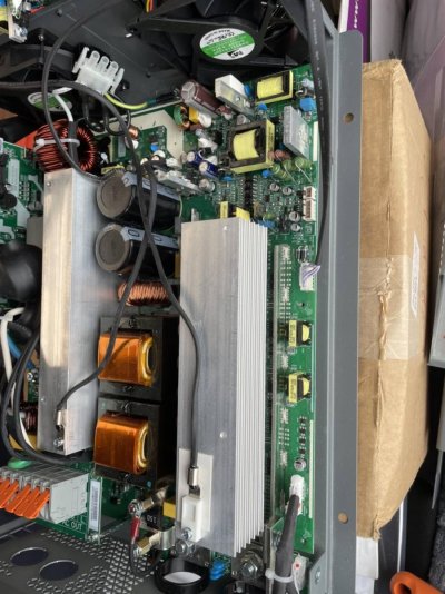
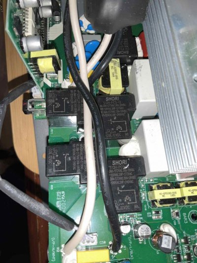
Here are some photos of the inverter inside. Where shall I measure first?

IMG_1151.jpgIMG_1152.jpgIMG_1153.jpgIMG_1154.jpgIMG_1155.jpgIMG_1156.jpg
 
IMG_1157.jpg

The full inside view.
There is no visible burning, coloring, swelling.
All three fuses check out.
 
The area next to the two transformers and the DC input is the input stage. We'll focus there first. Look at all the capacitors in this area. Any bulging? Measure resistance of all of them. Any shorted caps need to be replaced.

Next, identify the FETs in the input stage. They are mounted on a heatsink. There are likely four or eight of them. They have three pins. Measure resistance between the pins. They should not be shorted. One of the pins is connected to a thin trace (gate), the other two are connected to heavy traces (source, drain). Follow the thin trace to a small resistor. Measure all of them. They should be the same. Let me know what you find.
 
The way you described the damage to the unit and how it happened, I think it's something like this... The live section of the DC power was not hooked up and the AC shore power was live, a metallic socket fell in trough the holes. The AC input is on the AC in/out board upper left of your last picture. The socket would have had to touch the AC input terminals under that board and something else at the same time to cause damage, and it was only 3-4" long. The largest item in there that is conductive and easily touched is the heat sink for the FETS which is probably connected to the ground plane of the entire lower board.

So any component on the lower board is suspect and I'm going to say it's probably one of the surface mount logic level chips which would be most sensitive to that sort of a situation, they are all designed for 3.3V-5V DC. You can check FETs and caps, and those are common failure modes in normal operation, but knowing what happened and thinking of 120V AC being put to the ground plane of the board, I doubt that you'll find the problem.

There are various small surface mount components that provide oscillators, timing and generally control of the whole system. They are basically tiny computers and they are all tied to the ground plane as well, I'll bet that these components are where the issue lies.
 
The way you described the damage to the unit and how it happened, I think it's something like this... The live section of the DC power was not hooked up and the AC shore lies.


I am not saying you are incorrect. Although, I remember well that all connections were on. The stupid accident happened when I was trying to tie down the negative wire on the DC side. AC was all secured already and the positive on the DC. The negative wire was on the terminal and I was securing the nut on it. This is when the ratchet wrench socket fell inside.
The cover of the inverter was still on. At the end of the unit, where the connections are, a small cover section can be removed to make the connections with the wires. So, when the socket fell in, I could not see where did it go. There is a small opening between the components inside, so the socket could have gone only one way down, where it could bounce around a little. So, whatever it touched had to be at the lower section of the board.
Like I said I have not seen any burns, swelling or damage at that section. However, I can see burn marks at the AC IN wire section. I'll attach photos.

IMG_0014.jpgIMG_0015.jpgIMG_0016.jpg
 
Last edited:
Here we go.

There should be a row of FETs/transistors with heatsinks close to the input side. Each has three pins. Two of them (source and drain) have good sized copper traces going to them (they carry a lot of current). The other pin is the gate. Check resistance between the gate and the other two. It should not be shorted. Check resistance between the source and drain. Again should not be shorted. Do this for all FETs in the input side. If you find some that have different resistance than the rest, they are likely faulty and need to be replaced.
replacements.


I did the measurements you have suggested.

The 9 large capacitors all measure the same, 1.49 Mohms. These are the large brown colored one on the left side of the heat sink. No visual damage can be seen.

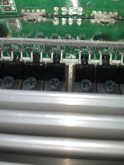
The FTEs are on the right side of the heat sink mounted at the bottom of the sink. I measured the legs from below on the main board. There total 12 of them.
The source/drain pair shows 4.99 Kohms. All the same.
The left leg/gate pair shows 1.41-1.43 Mohms.
The right leg/gate pair shows 14.1-14.3 Kohms.
I don't know which is the source and the drain, so I call them left/right as I was facing the board strait up.

I took some more photos.
The photos show that some of the FTEs have something flown over, so the letters are not visible. It looks like a type of glue. It could be a result of manufacturing.

IMG_0005.jpgIMG_0006.jpgIMG_0011.jpgIMG_0012.jpgIMG_0013.jpg
 
Last edited:
Have just repaired an old Raytheon hailer and found similar goo on two capacitors, I believe it is dielectric silicon-not leakage. It's purpose is unknown to me.

Tator
 
Steve noticed Mastervolt was not on your list. Last year the P.O. replaced his Victron (which failed) with a Master Volt. Is this a component I’d need to be concerned about?
 
Good news. Looks like the input section FETs (Field Effect Transistors) are OK. They rarely fail open. Do the same measurements in the output section. This is the section that converts the 160V DC to AC. Measure the FETs and caps as before.

Also measure the resistance on the DC input terminals and the AC input/output terminals.
 
The FETs would be mounted with a heat transfer paste, that might be what you are seeing.

Understood about the socket, hard to say what was touched, if the DC was also connected then there's a wider range of things that could have been damaged.

You might also check the two transformers next to the FETs, these are part of the circuit used to boost the voltage.
 
Good news. Looks like the input section FETs (Field Effect Transistors) are OK. They rarely fail open. Do the same measurements in the output section. This is the section that converts the 160V DC to AC. Measure the FETs and caps as before.

Also measure the resistance on the DC input terminals and the AC input/output terminals.


Well, here are the results. This was much more difficult, because it is hard to see anything and the boat is rocking constantly for the last few days. I've made few more pictures of the FTE section.

DC terminal + shows 0.3 ohm
DC terminal - shows 0.4 ohm

AC terminals all 0.3-0.4 ohm

2 large white capacitors on the left of the grill show 3.52 Mohms
3 medium orange capacitors show 10.1 Mohms at start and the number keep going down slowly

FTE
I am not sure how many they are. It seems total of 9, but I cannot see from the front. I will list 9 measurements, but it could be only 8 of them.
Starting from the bottom one and going up.
Leg left with center - 1.95 Mohm
Leg left with leg right - 38.2 Kohm
Leg center with leg right - 1.95 Mohm

Leg left with center - 1.56 Mohms
Leg left with leg right - 38.4 Kohms
Leg center with leg right - 1.58 Mohm

Leg left with center - 0.625 Mohms
Leg left with leg right - 38 Kohms
Leg center with leg right - 0.626 Mohm

Leg left with center - 4.19 Mohms
Leg left with leg right - 36.6 Kohms
Leg center with leg right - 4.24 Mohm

Leg left with center - 12.82 Mohms
Leg left with leg right - 22.6 ohms
Leg center with leg right - 12.85 Mohm

Leg left with center - 12.54 Mohms
Leg left with leg right - 22.6 ohms
Leg center with leg right - 12.49 Mohm

Leg left with center - 12.54 Mohms
Leg left with leg right - 22.7 ohms
Leg center with leg right - 12.51 Mohm

Leg left with center - 12.42 Mohms
Leg left with leg right - 22.6 ohms
Leg center with leg right - 12.40 Mohm

?
Leg left with center - 3.66 Mohms
Leg left with leg right - 31.1 Kohms
Leg center with leg right - 3.72 Mohms


IMG_0021.jpgIMG_0024.jpgIMG_0025.jpgIMG_0015.jpgIMG_0016.jpg
 

Attachments

  • IMG_0016.jpg
    IMG_0016.jpg
    154.4 KB · Views: 15
Last edited:
Neither the DC in nor the AC in /out sections should be shorted. The 0.x Ohms you see are just the resistance of your leads.

Something is not quite right with your measurements. You measured the input sections FETs and caps with high resistance but the DC in section shows a short. There is not much between the DC input terminals and the input section FETs.

Follow the heavy traces on the DC input side. Keep measuring resistance. Eventually you should arrive at the input section FETs. Measure resistance between the two heavy traces on a FET. It should have the same resistance as what you are measuring at the DC input side.


Did you mean AC side FTE ?

Where is the short on DC side?

What is considered short, how much resistance?

Forgive my questions, but you are talking to a novice here....
 
You mentioned that the AC outputs were already connected. If the AC's so called neutral (grounded conductor) was connected to the boat's bonding system at the time you were connecting the DC to the inverter, that would have immediately caused either a 12V circuit breaker to trip and maybe save the inverter OR killed the 4 FETs in the inverter's output H bridge. And yes, FETs can fail open or shorted. Just my thoughts-
 
You mentioned that the AC outputs were already connected. If the AC's so called neutral (grounded conductor) was connected to the boat's bonding system at the time you were connecting the DC to the inverter, that would have immediately caused either a 12V circuit breaker to trip and maybe save the inverter OR killed the 4 FETs in the inverter's output H bridge. And yes, FETs can fail open or shorted. Just my thoughts-


Inverter's output H bridge means the AC side? The FTEs I have measured yesterday, with those odd numbers? Based on the numbers are listed, which FTE is dead? Are they expensive? Is it worth trying to replace them?

Yes, all AC wires were connected securely, when the accident happened.
 

Latest posts

Back
Top Bottom