Marco Flamingo
Guru
- Joined
- Jan 7, 2020
- Messages
- 1,110
- Location
- United States
- Vessel Name
- CHiTON
- Vessel Make
- Tung Hwa Clipper 30
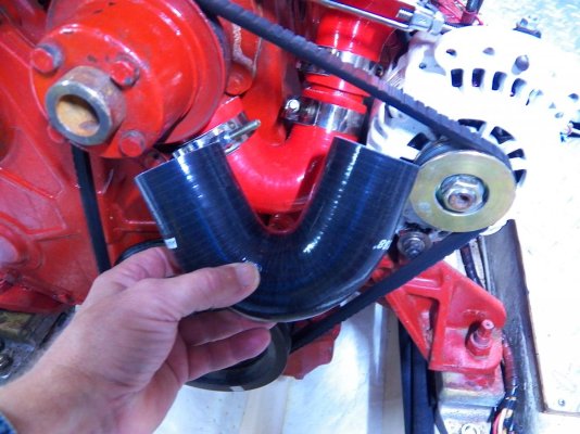
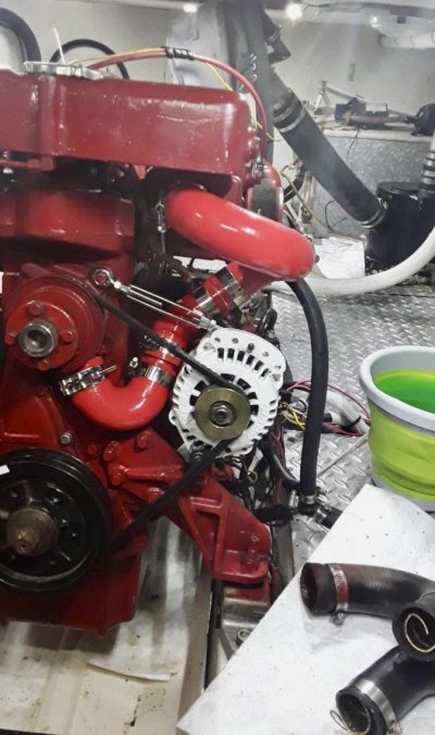
This project started out as the alternator hack using a turnbuckle as in other threads. While replacing the alternator arm with the turnbuckle, I noticed that my original arm was different than some. Some Lehmans have a curved arm that attaches to the lower bolt on the water pump and the alternator (second picture). That doesn't leave a "sneak route" for a coolant hose to avoid passing through the fan belt. By attaching the alternator turnbuckle to the upper bolt on the water pump, I thought I might be able to purchase off-the-shelf silicon hose pieces and fabricate a hose that allowed easier fan belt replacement.
I removed my original coolant hose and found that it was not in great shape. It appears that it had a wire coil inserted in it to keep the bends from collapsing. You can see the wire inside in the upper right in the first (sideways) picture. This isn't the wire imbedded in the rubber hose coming loose. It's a separate wire coil. The old hose ends were splitting, there were soft spots, and the cheese-grater style hose clamps had dug in fairly deep.
I also had an old fan belt wrapped around the coolant hose so that a fan belt could be replaced without removing the hose (the original Lehman hack to simplify replacing a broken belt). The belt was of unknown vintage. I thought that as long as I was replacing the coolant hose, I'd try a hack. The 4 red silicon hose bends and new clamps were less than $100. I didn't look to see what a new standard Lehman hose would be. I now have a new coolant hose and a fan belt that can be quickly replaced without the use of tools.
Attachments
Last edited by a moderator: