Keel cooling water path

The friendliest place on the web for anyone who enjoys boating.
If you have answers, please help by responding to the unanswered posts.

GoneDiving

Senior Member
Joined
Jul 24, 2019
Messages
499
Location
Australia
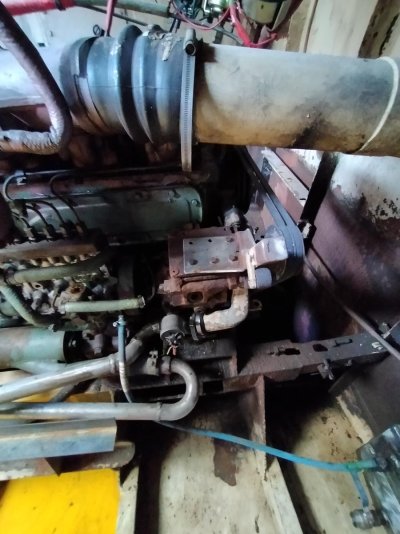
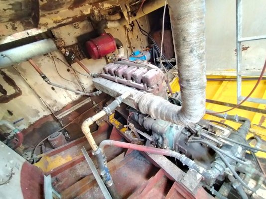
One of the many "when I get to it" jobs is to tidy up the keel cooling plumbing in my engine bay.

What is the typical water path for these systems?I would have thought that the engine water jacket and oil coolers would have been first in line for the coldest coolant. However, my system runs:

Keel cooler cold side
Exhaust water jacket
Header tank
Thermostat
Engine inlet
Engine block
Water pump
Engine oil cooler
Gear box cooler
Keel cooler hot side

Over heating has never been a problem and it's worked this way for >30 yrs. I'd just like to move some of the piping out of the way and improve appearances.

Comments?
 
A keel cooler should be plumbed as if it was a radiator or heat exchanger. That usually means entering at the thermostat. The fact that you haven't had over heating problems is more the way you operate the boat, the rpm and the amount of hp being used.
 
Any chance of some pictures? What's the engine? And what parts of the plumbing are you hoping to improve?


It does seem that the gear cooler is on the wrong end of the loop. Have you measured gear oil temp? What are the gear specs for allowed oil temp? On the ZF and Twin Disc gears I've had, the only way to have the oil temp in spec is to put the gear cooler on the cold outlet side of the keel cooler flow so it's first in line in the coolest spot.
 
I believe you are tracing your water path backwards. On most engines, the coolant is entering the engine at the circulating pump (lower hose) and leaving at the thermostat housing (upper) hose. Assuming this is correct, and the order of operations is backwards, it would make a lot more sense.
 
For longest engine life an external bypass thermostat helps with cooling shock.

A proper keel cooler is created for full power in tropical water with modest fouling on the cooler.

This results in over cooling the circ. water most of the time.
The usual OTR truck radiator setup lowers the coolant by only 20deg F or so..

The technique in a vessel is a thermostat between the hot engine output and the much cooler returning water..

The thermostat in the engine is only setup to allow the engine coolant to depart at a specific temperature , feeding cold water to the engine creates a thermal shock the engines thermostat can not control.


Lots of boats don't bother and get OK service lives , but it is the proper setup for keel cooling.
 
Last edited:
Thanks guys. I've done a little more research and it looks as if gdavid is correct.

OEM has cooled water being sucked through the oil cooler into the block, heated and returned to the radiator header tank. It appears my trans cooler, keel cooler and exhaust jacket have been added upstream to the oil cooler in that order. As I said, it has all worked for 30 years as I have no problems with over heating in tropical North Australia. However, pipes are in awkward locations and need to be climbed over to get around the engine bay. That was my main concern. Now I'll confirm if the keel coolers are indeed operating on the suction side of the system. This is obviously less than ideal if there is a minor pin hole or major break develops.

For reference, the mains is a 200hp Mercedes OM355. Very popular here years ago in commercial fishing fleets but to my knowledge they are marinised on a case by case basis rather than being offered as an OEM marine package. Never the less, it's been bullet proof to date.

Thanks again
 
Assuming that the thermostat and temp sender are on the outlet side of the water jacket, then everyone was correct: my initial description had the coolant flow backwards and the trans, keel and exhaust coolers have been added to the suction side of the oil cooler.

Definitely something I'll correct when I make the piping more access friendly.
 

Attachments

  • IMG20210804110240.jpg
    IMG20210804110240.jpg
    124.6 KB · Views: 3
  • IMG20210804110222.jpg
    IMG20210804110222.jpg
    164.3 KB · Views: 7
  • IMG20210804110440.jpg
    IMG20210804110440.jpg
    191.9 KB · Views: 13
  • IMG20210804110404.jpg
    IMG20210804110404.jpg
    154.4 KB · Views: 9
  • IMG20210804110345.jpg
    IMG20210804110345.jpg
    151.2 KB · Views: 3
  • IMG20210804110318.jpg
    IMG20210804110318.jpg
    180.2 KB · Views: 7
For reference some OEM non marinised photos

Thanks everyone
 

Attachments

  • Screenshot_2021-08-05-02-14-21-53_40deb401b9ffe8e1df2f1cc5ba480b12.jpg
    Screenshot_2021-08-05-02-14-21-53_40deb401b9ffe8e1df2f1cc5ba480b12.jpg
    68.2 KB · Views: 3
  • Screenshot_2021-08-05-02-15-30-89_40deb401b9ffe8e1df2f1cc5ba480b12.jpg
    Screenshot_2021-08-05-02-15-30-89_40deb401b9ffe8e1df2f1cc5ba480b12.jpg
    89.3 KB · Views: 5
  • Screenshot_2021-08-05-02-17-15-68_40deb401b9ffe8e1df2f1cc5ba480b12.jpg
    Screenshot_2021-08-05-02-17-15-68_40deb401b9ffe8e1df2f1cc5ba480b12.jpg
    73.4 KB · Views: 4
Back
Top Bottom