Adding electric outlets where I want them

The friendliest place on the web for anyone who enjoys boating.
If you have answers, please help by responding to the unanswered posts.
Joined
Jul 3, 2016
Messages
1,439
Location
USA
Vessel Name
Escape
Vessel Make
Mariner 37
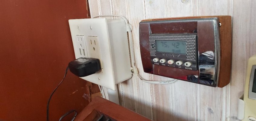
My boat has plenty of outlets, but there are none where we work and that means charging cables and extension cords draped across traffic areas. Adding outlets would be simple if this problem was at our dirt home, but I am far less familiar with ABYC and marine wiring.

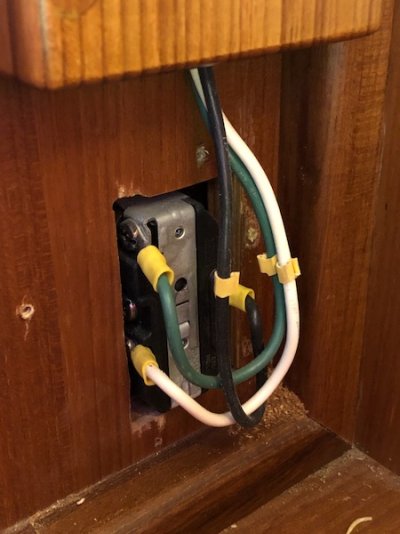
Mariner built the boat using wood covers on the back sides of what look like standard household 120 VAC outlets. Instead of your basic Romex, they used suitable gauge individual strand braided wire. I know about terminating connections with crimp on ends and not using wire nuts.

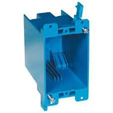
I don't plan to build wood boxes as my woodworking skills fall well short of the Taiwanese craftsmen that built the originals. What about your basic plastic old work single gang boxes as a backer? One outlet will be in a "utility" area housing an air conditioner unit and the other will be in a rather inaccessible upper corner of a cabinet. What is the right approach?
 

Attachments

  • IMG_7963.jpeg
    IMG_7963.jpeg
    73.5 KB · Views: 36
Big box store,grey outdoor plastic, spray painted white
 

Attachments

  • thumbnail21.jpg
    thumbnail21.jpg
    67.7 KB · Views: 39
I have used the blue plastic boxes. Also use adhesive lined heat shrink connectors on the wires. It appears that the connectors on the outlet in the photo do not have the heat shrink connectors.
 
Yes they aren't pretty but psneeld's use of box outlets works. The only problem will be hiding the wires where fingers can't touch them or use surface raceway to cover them. You don't have to use Romex cable, individual insulated wires are ok.

But you might consider adding a bank of USB charging outlets as well while you are at it. Most phones and tablets use them to charge with. These can be either AC or DC powered.

David

David
 
Good reminder about the USB outlets. We replaced all of the outlets in our last boat and put at least one with the builtin USB ports in each room and two in the master cabin.
 
Yep, one of the first additions I did on our boat was to add double USB outlets at both helms. Tapped into the 12v outlet circuit - using marine 16 'romex'. We use them all the time :thumb:
 
We added a 12 volt outlet but also a bunch of ones that are 120 volt with USB ports builtin.
 
also a bunch of ones that are 120 volt with USB ports builtin.

Ditto for me, but mine were slower charging usb ports, now I get the ones with fast charge instead.
 
I have read about the combo USB units and examined them at the hardware stored today. Might have bought a pair except they have prominent ventilation grates in the outlet rear housing and that reminded me how warm the plug in kind get. No problem dealing with the heat they produce?
 
No problems with heat - plenty of uncluttered space behind them, and they are the fast- charge types.
 
I used these. No problem with heat while we had the boat.

Leviton T5632-E USB Charger/Tamper-Resistant Duplex Receptacle, 15-Amp, Black, 1-Pack
 
In the photo I posted, the left outlet has 2 USB chargers. Leviton from Lowes.


Yes they are not quick chargers, but unless we need a quick charge they are fine, if not, use the quick charge wall wart in the same outlet.
 
One issue I ran into in dealing with outlets and such - you often need to connect 3 wires together (incoming, outgoing, and splitting off for a device, the outlet, etc...).

I guess the "proper" way to do this is with a screw terminal bus strip? Maybe use a double wide box, with a blank on one side that you put the terminal strip in, and put the outlet in the other side?


Usually an outlet has line and load ...what else do you need?


What "device" are you talking about?
 
I've often seen cases where there was a line that came in that supplied power, and then a line (sometimes two) going out to the next outlet or light...

On a traditional home outlet, you at least have two terminals, so you could put the incoming line on one, and the outgoing line on another.

What I'd LIKE to do is replace all of my outlets with GFI outlets, and not use the "load" side going out. GFI outlets have one set of terminals for the input. I could crimp proper terminals on the incoming and outgoing, and technically get away with having two terminals under the same single screw (right?) - but it's tough to do...
 
I hate how they wire houses where the first outlet is a GFI, and then there are some random number of following outlets on the "load" side of the GFI. Then any of the down stream outlets can cause the GFI to trip, and in many cases you're scratching your head wondering what tripped!

I had that happen once on a Sea Ray. The GFI outlet was on the underside of a cabinet. Took FOREVER to figure out why I wasn't getting power at some of the outlets. Happened to be working on something else - happened to see the GFI, and finally connected the dots... Hence my preference that a GFI should ONLY protect that one outlet, and NOT have downstream stuff on the "load side" where it's not obvious what's connected to what...

You will probably have to run new power cables to the 2nd and successive outlets since the boat builder will power the 2nd outlet off the first. The normal method is to put the GFI on the first outlet that needs protection and then it will protect the outlets daisy chained off the GFI. This is the normal and accepted way of doing it. Nothing wrong with only 1 outlet on the GFI but you will have to add more wiring and breakers to supply the wiring. Most boats don’t have a lot of extra breakers.
 
One issue I ran into in dealing with outlets and such - you often need to connect 3 wires together (incoming, outgoing, and splitting off for a device, the outlet, etc...).

I guess the "proper" way to do this is with a screw terminal bus strip? Maybe use a double wide box, with a blank on one side that you put the terminal strip in, and put the outlet in the other side?

There usually isn’t 3 wires, just incoming and outgoing. The device is where they get connected. In the unusual case where you have 3 wires to connect together a bus bar or terminal strip is the correct way to connect them.
 
I hate how they wire houses where the first outlet is a GFI, and then there are some random number of following outlets on the "load" side of the GFI. Then any of the down stream outlets can cause the GFI to trip, and in many cases you're scratching your head wondering what tripped!

I had that happen once on a Sea Ray. The GFI outlet was on the underside of a cabinet. Took FOREVER to figure out why I wasn't getting power at some of the outlets. Happened to be working on something else - happened to see the GFI, and finally connected the dots... Hence my preference that a GFI should ONLY protect that one outlet, and NOT have downstream stuff on the "load side" where it's not obvious what's connected to what...


Wow...you are the first person to want to do it differently than I have met. You seem to be looking for a solution for where there is no problem...and maybe making things worse as I have never heard of people doing GFIs the way you suggest.


Sure finding the offensive GFI the first time is a pain, but after that most people learn.
 
Last edited:
I'm willing to spend the $10 per outlet (buying in bulk) to put one GFI at each place. Then, if something trips, the reset is right there where whatever it is plugs in.
If I did the wiring, I *might* remember where the master GFI outlet is on a circuit... But several years later (when, not if, I forget), or for guests, or if I ever sell the boat - it would sure be nice to not have to go hunting for a GFI outlet somewhere else.

But unfortunately, it does complicate the wiring.

Another place I ran into a similar conundrum was in the engine room. Incoming AC supply line, but I wanted to use that for a set of LED lights for the engine room, an engine room heater, and ideally a spare plug for power tools, pumps, etc...

The easy solution would have been to install an outlet or two, but I got mixed answers on whether or not it was ok to have outlets in the engine room of a gas powered boat.

I CLEARLY understand the risk of spark when you plug / unplug something. But I also think any REASONABLE person wouldn't try to plug something into an outlet when they could smell gas fumes. And hopefully I'd never have (unreasonable) people down in the engine room...
 
Chaining outlets is usually limited to one or two outlets so usually there is no challenge to find what outlet is triggering the breaker as it is the one you are using.

L
 
I'm willing to spend the $10 per outlet (buying in bulk) to put one GFI at each place. Then, if something trips, the reset is right there where whatever it is plugs in.
If I did the wiring, I *might* remember where the master GFI outlet is on a circuit... But several years later (when, not if, I forget), or for guests, or if I ever sell the boat - it would sure be nice to not have to go hunting for a GFI outlet somewhere else.

But unfortunately, it does complicate the wiring.

Another place I ran into a similar conundrum was in the engine room. Incoming AC supply line, but I wanted to use that for a set of LED lights for the engine room, an engine room heater, and ideally a spare plug for power tools, pumps, etc...

The easy solution would have been to install an outlet or two, but I got mixed answers on whether or not it was ok to have outlets in the engine room of a gas powered boat.

I CLEARLY understand the risk of spark when you plug / unplug something. But I also think any REASONABLE person wouldn't try to plug something into an outlet when they could smell gas fumes. And hopefully I'd never have (unreasonable) people down in the engine room...


It isn’t the cost of the GFIs. It is the wiring. You can’t have daisy chained GFIs so each GFI would have to be on its own circuit. So you have to add a lot of breakers and a lot of wiring runs to each outlet. Maybe better to just do it the accepted method and document where the GFIs are.

You absolutely should not have unprotected outlets in a gas powered engine room. Your insurance would most likely cancel your insurance if they find out. If you did have an explosion they most likely wouldn’t pay because you did the outlet in the engine room. So just run an extension cord when you need power there but don’t plug non ignition protected things into it like a shop vac. Anything electrical that goes into the engine room of a gas powered boat should be ignition protected, which limits what you can use down there. Yes it is a PITA, but it is protecting you and anyone aboard, and maybe the boats next to you.
 
Commodave, you've said this twice about needing a separate circuit for each GFI - and I am missing why that is necessary.

If the breaker feeds the LINE side of the first GFI, and then you go from that same LINE side (not the LOAD side) to the next GFI - why can't you have multiple outlets on the same breaker? Granted, that would have two sets of wires on the LINE side. Is that what you're assuming wouldn't be done? And obviously, you couldn't pull 15A from each outlet all at the same time.
 
...I CLEARLY understand the risk of spark when you plug / unplug something. But I also think any REASONABLE person wouldn't try to plug something into an outlet when they could smell gas fumes. And hopefully I'd never have (unreasonable) people down in the engine room...
UK, USA, probably other places, have no switch on GPOs. Australia does, boats here too, it overcomes spark on insert/remove. But I guess the switch inside the box could spark, on/off.
 
Costco has carried twin packs of USB outlets for years. Often on sale. I think I paid $15 for this pair. Hi-output USB (my Samsung tablet won't charge without hi-output)

Blue "old work" boxes are fine. As far as GFI and daisy-chaining, I don't understand the statements that new circuit/wires must be run if a separate GFI is desired at downstream outlets (but I only breezed fhis thread, so maybe I missed somethjng). You don't have to connect the downstream wires to the protected side of the GFI. Connect to the unprotected terminals and either have an unprotected outlet downstream, or install a separate GFI.

Peter 20210720_061150.jpg
 
I like the blue electrical boxes that have little tabs connected to the screws, these can be flush mounted even when you have minimal access to the backside of the panel. You just cut you rectangular hole, snake your wire, run it into the backside of the box and when you start to turn the screws, the tabs swing out and eventual tighten up against the back side of the panel.
 

Attachments

  • electrical box with tabs.jpg
    electrical box with tabs.jpg
    4.7 KB · Views: 148
Thanks for all the detail, guys. It all seems pretty straightforward.

What about wire? I get the need for braided and connector terminations, but any reason not to use Romex or a competitor’s “combination” cable instead of individually insulated conductors like Mariner did when they built my boat in 2007?


No problem using a multi conductor cable, but it can't be Romex, as it needs to be stranded, not solid conductor. Multi conductor stranded marine cable is available for stuff like this.
 
Sorry for the confusion; I refer to Romex as the brand rather than the generic type of cable. Romex does make stranded conductor cable.
 
Sorry for the confusion; I refer to Romex as the brand rather than the generic type of cable. Romex does make stranded conductor cable.


Gotcha. I prefer to use tinned cable, but as long as it's stranded, it'll do the job.
 
Back
Top Bottom