A little help please?

The friendliest place on the web for anyone who enjoys boating.
If you have answers, please help by responding to the unanswered posts.

JAT

Guru
Joined
Jan 30, 2010
Messages
595
Location
US
Vessel Name
Just a Tinch
Vessel Make
Gulfstar 44 MC
Here's what I have.... I have constructed a new house bank with 6 - 6volt batteries that are properly connected in series so that each pair is 12 volts.

Now...I have an automatic 40A charger.... and I also have a generator starting battery and an engine starting battery.

Do I wire the house bank with the 6 - 6volts wired in series as one bank, or do I wire each pair as a bank?

Do I wire the other two batteries independently to the charger if I only use one positive lead to the 6-6 volt bank in series?

From what I have read...it would seem you can do either way...but what I would like to know...is what is the BEST way to do it?

Thanks
 
I would wire the house bank as one bank, starting batteries as another. Will your charger do 3 banks separately? Here is the way that I have Moonstruck set up. Each bank is separate, but can be tied together with an emergency parallel switch. I have twin engines, so the port alternator charges the house bank and the starboard the starting bank. Hope this helps.

img_101772_0_ca24dfd839d48c7f3ce286c1fea80d1e.jpg
 
The charger is a 3 bank Mastervolt automatic 40A charger. Its not the real fancy one that integrates into their total system....but is just a charger that accommodates a remote readout panel.
 
The charger is a 3 bank Mastervolt automatic 40A charger. Its not the real fancy one that integrates into their total system....but is just a charger that accommodates a remote readout panel.

That would work just fine in my setup.
 
Thanks!!
 
For what it's worth here is the battery charger in Moonstruck.

img_101786_0_05e0dbb790ccfef2aab2becdf6f27e84.jpg
 
Moonstruck, it's nice to see wiring that isn't a rat's nest.
 
I agree with Moonstruck. The six 6v batteries are one house bank with the 3 series pairs (to get 12V) connected in parallel to provide the ~660AH capacity at 12V. A set of charger hot and ground wires connect to this bank at opposite ends of the bank. There are diagrams online that depict that show the proper rigging for the cables and charger leads.

The start battery and the genset battery are separate banks and connect to separate sets of charger leads.
 
Moonstruck, it's nice to see wiring that isn't a rat's nest.

Thanks Mark. I just like to make it easy to trace things down.

By the way, I put out a BOLO for you on the off topic section. I had heard the Master and Commander was lost.
 
The concept is the higher voltage the batt set is at , the less damage from being discharged.

So a BIG house bank of 6 batts will handle the loads , and live longer than 3 pairs of 2 batts in rotation.
 
Thanks everyone... This site is a great resource!!
 
Thanks Mark. I just like to make it easy to trace things down.

By the way, I put out a BOLO for you on the off topic section. I had heard the Master and Commander was lost.

No. I was in England, Belgium, Netherlands, and mostly Germany for ten days last month. The trip cost only two boat-bucks, a small fraction of my recent visit to the boatyard.
 
Last edited:
Having separate switches, one for the house batteries, one for the engine/starting, and a third switch to connect/parallel them is a good idea.

img_101961_0_76a265980c8a968302df6c766b97acec.jpg


An inverter is helpful if you have 110 systems onboard. The Coot has 110-AC interior outlets as well as water-heater and air-compressor on AC.

img_101961_1_7c183f20ca79c516b16aad4f9b15e879.jpg
 
Last edited:
My 3-bank charger fried the generator battery prematurely, so after replacing the genset battery, I did not reconnect it to the charger. Instead, I connected it to the house bank via an echo charger. As I understand it, even if a charger can charge 3 different banks, that only means that it doesn't combine the banks. The battery banks will be charged the same even if there is a bank that didn't need charging (hence the frying).

I hope I did the right thing, but I read a post from Larry M. here that his generator battery is only being charged by the generator. I think that this makes more sense as these batteries really don't need much charging. Maybe when I use my boat more regularly I will copy Larry's set-up. My genny sometimes goes for 3 months without use, so some charging is needed to keep the battery from dying.

So if you use the generator regularly you may not need to connect it to the charger. And the same goes for the engine starting batteries. Just a thought.
 
"these batteries really don't need much charging.


A wet bat will loose 1% to 3% daily .


My genny sometimes goes for 3 months without use, so some charging is needed to keep the battery from dying"
.

You bet , good use for a solar panel.
 
Well, I went to my favorite marine surplus store in Sarasota...picked up some #4 cable and some lugs....went back and put the new charger in and wired it all up. The house bank of 6v's is wired in correctly, and my other two batteries are "separate banks".... This works out good...the previous charger fried my echo charger..... Now all is good!!

Thanks again.... :D
 
Please explain why you think that is so.

According to the "sperts" using the entire bank makes the battset last longer , for the same work over time.

Seems the First bat in the string works harder than the rest if not properly hooked up. Harder work= fewer cycles it can recover from.
 
Please explain why you think that is so.

from: SmartGauge Electronics - Interconnecting multiple batteries to form one larger bank

--------------------------------------------------------------------
How to correctly interconnect multiple batteries to form one larger bank.
Two things I have noticed in my (more than) 20 years in this business are that:-
A. Many "specialists" simply tell you..... "do it this way, this is the correct way" without ever showing why they consider it to be the correct way, and often it isn't, which is perhaps why they couldn't show you why it is(!)
B. Some things have been done for so long, in a certain manner, that it seems they must be the best way of doing it. Otherwise why hasn't another method appeared?
Here at SmartGauge Electronics we always show you why one method is better. We don't expect you to take our word for it. We will happily use practical examples, theory, maths or whatever else it takes to show the results of various ways of doing things.
Interconnecting multiple batteries to form one larger bank is one case in point. Though in this case, newer methods have emerged over the years. Unfortunatley they still aren't perfect.
Here is a diagram showing the old way of interconnecting 4 batteries to form one larger bank. This is a method that we still see in many installations.

batt_old.gif


Method 1
Notice that the connections to the main installation are all taken from one end, i.e. from the end battery.
The interconnecting leads will have some resistance. It will be low, but it still exists, and at the level of charge and discharge currents we see in these installations, the resistance will be significant in that it will have a measurable effect. Typically the batteries are linked together with 35mm cable in a good installation (often much smaller in a poor installation). 35mm copper cable has a resistance of around 0.0006 Ohms per metre so the 20cm length between each battery will have a resistance of 0.00012 Ohms. This, admittedly, is close to nothing. But add onto this the 0.0002 Ohms for each connection interface (i.e. cable to crimp, crimp to battery post etc) and we find that the resistance between each battery post is around 0.0015 Ohms.


If we draw 100 amps from this battery bank we will effectively be drawing 25 amps from each battery. Or so we think.
In actual fact what we find is that more current is drawn from the bottom battery, with the current draw getting progressively less as we get towards the top of the diagram.
The effect is greater than would be expected.
Whilst this diagram looks simple, the calculation is incredibly difficult to do completely because the internal resistance of the batteries affects the outcome so much.
However look at where the load would be connected. It is clear that the power coming from the bottom battery only has to travel through the main connection leads. The power from the next battery up has to travel through the same main connection leads but in addition also has to travel through the 2 interconnecting leads to the next battery. The next battery up has to go through 4 sets of interconnecting leads. The top one has to go through 6 sets of interconnecting leads. So the top battery will be providing much less current than the bottom battery.
During charging exactly the same thing happens, the bottom battery gets charged with a higher current than the top battery.
The result is that the bottom battery is worked harder, discharged harder, charged harder. It fails earlier. The batteries are not being treated equally.
Now in all fairness, many people say "but the difference is negligible, the resistances are so small, so the effect will also be small".
The problem is that in very low resistance circuits (as we have here) huge differences in current can be produced by tiny variations in battery voltage. I'm not going to produce the calculations here because they really are quite horrific. I actually used a PC based simulator to produce these results because it is simply too time consuming to do them by hand.
Battery internal resistance = 0.02 Ohms
Interconnecting lead resistance = 0.0015 Ohms per link
Total load on batteries = 100 amps

The bottom battery provides 35.9 amps of this.
The next battery up provides 26.2 amps.
The next battery up provides 20.4 amps.
The top battery provides 17.8 amps.

So the bottom battery provides over twice the current of the top battery.
This is an enormous imbalance between the batteries. The bottom battery is being worked over twice as hard as the top battery. The effects of this are rather complex and do not mean that the life of the bottom battery will be half that of the top battery, because as the bottom battery loses capacity quicker (due to it being worked harder) the other three batteries will start to take more of the load. But the nett effect is that the battery bank, as a whole, ages much quicker than with proper balancing.
I have to be honest now and say that when I first did this calculation in about 1990 I completely refused to believe the results. The results seemed so exaggerated. So much so that I wired up a battery bank and did the experiment for real, taking real measurements. The calculations were indeed correct.
batt_new.gif


Method 2
All that has changed in this diagram is that the main feeds to the rest of the installation are now taken from diagonally opposite posts.
It is simple to achieve but the difference in the results are truly astounding for such a simple modification.
The connecting leads, in fact, everything else in the installation remains identical.
Also, it doesn't matter which lead (positive or negative) is moved, Whichever is easiest is the correct one to move.
The results of this modification, when compared to the original diagram are shown below. Only that one single connection has been moved.


After this simple modification, with the same 100 amp load....
The bottom battery provides 26.7 amps of this.
The next battery up provides 23.2 amps.
The top battery provides 26.7 amps.

This is quite clearly a massive improvement over the first method. The batteries are much closer to being correctly balanced. However they are still not perfectly balanced.
How far is it necessary to go to get the matching equal?
Well, the better the quality of the batteries, the more important it becomes. The lower the internal resistance of the batteries, the more important it is to get them properly balanced.
So that now leaves the question of whether or not there is a wiring method to perfectly balance the batteries.
Before getting to that, it should be pointed out that doing the calculation is not actually required in order to arrive at the ultimate interconnection method. I simply did them to show the magnitude of the problem.
In order to get a better balancing it is simply necessary to get the number of interconnecting links as close as equal between each battery and the final loads.
In the first example the power from the bottom battery passed through no interconnecting links. The top battery passed through 6 links.
In the 2nd example (the much improved one), the power from the top and bottom battery both passed through a total of 3 links. That from the middle 2 batteries also both passed through 3 links which begs the question "why were they not therefore perfectly balanced?". The answer is that some of the links have to pass more total current and this therefore increases the voltage drop along their length.
And now we get to the correctly wired version where all the batteries are perfectly balanced.
batt_v_new.gif

Method 3
This looks more complicated.
It is actually quite simple to achieve but requires two extra interconnectng links and two terminal posts.
Note that it is important that all 4 links on each side are the same length otherwise one of the main benefits (that of equal resistance between each battery and the loads) is lost. The difference in results between this and the 2nd example are much smaller than the differences between the 1st and 2nd (which are enormous) but with expensive batteries it might be worth the additional work. Most people (myself included) don't consider the expense and time to be worthwhile unless expensive batteries are being fitted or if the number of batteries exceeds 8.


This method isn't always so easy to install because of the required terminal posts. In some installations there is simply no room to fit these. So, thanks to a colleague, we can also present another wiring method that achieves perfect battery balancing...............
batt_new_2.gif

Method 4
And here it is.
This looks odd but it's actually quite simple. What has been done here is to start with 2 pairs of batteries. Each wired in the proper "cross diagonal" method. Then each pair is wired together, again in the cross diagonal method.
Notice that for each individual battery, the current always goes through a total of one long link and one short link before reaching the loads. This method also achieves perfect balance between all 4 batteries and may be easier to wire up in some installations. Many thanks to "smileypete" from Canal World Discussion Forums for this idea.


There really is no excuse whatsoever (apart from, perhaps, incompetence or laziness) for using the first example given at the top of this page.
The other three methods achieve much better balancing with the final two achieving perfect balancing between all four batteries.
I think I am right in saying that this is the only example I have ever come across where doing something the correct way actually looks less elegant than doing it incorrectly.
Finally, if you only have 2 batteries, then simply linking them together and taking the main feeds from diagonally opposite corners cannot be improved upon.
Once the number of batteries gets to 3 or more then these other methods have to be looked at.
With a large number of batteries it may be necessary to go to the 3rd method shown above.
Even with 8 batteries it is possible to get reasonable balancing by placing the main "take off" feeds from somewhere down the chain instead of from the end batteries. Remember, count the number of links each battery needs to run through to reach the final loads and get these as equal as possible.
Finally, if your battery bank has various take off points on different batteries, change it now! It is extremely bad practice. Not only does it mess up the battery balancing, it also makes trouble shooting very much more complicated and looks awful. And finally, finally, we keep getting asked where the chargers should be connected to. We didn't address this question because it seemed so blatantly obvious where they should be connected that it never occurred to us that anyone might be unsure. The chargers should always be connected to the same points as the loads. Without exception.
-----------------------------------------------------------------------

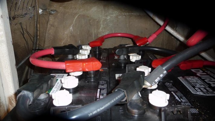
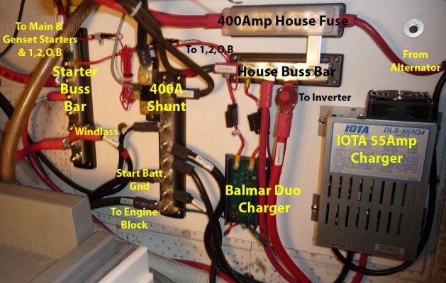
The attached diagram is from 94 Battery Wiring Diagrams . Note that in all examples, the + and - leads are connected at opposite ends to pull the load THROUGH the entire bank.
 

Attachments

  • 12VBanks.jpg
    12VBanks.jpg
    29.8 KB · Views: 115
Last edited:
OK Flywright here we go.

The reference above cites 35MM as the standard wire size for a bank of batteries. Since I'm in the USA I tried to cross reference 35mm wire to AWG to see what size wire we're talking about.

Here's a link to the cross reference I found

American wire gauge - Wikipedia, the free encyclopedia

It appears that the 35MM wire cited in your post is somewhere between 1 and 2 AWG.

I believe that many of our house banks are similar to mine. I have four L16HC 6 volt batteries totaling 840 amp hours. They are interconnected with 4/0 AWG wire which is a heck of allot larger and much less resistance.

Normal charge rate for bulk charging is around 120 amps, then decreasing from there as the regulator switches modes.

Discharge rate for my bank averages about 25 amps.

While the article is interesting, and I enjoyed reading it on a professional level, it may not be as applicable to the actual use in our boats as it might at first glance seem.

One of the the specific reasons it may not be as applicable as it seems is that it uses 100 amps as a test amperage. That amperage is not valid for a long term discharge amperage, although is is partially valid for recharging.

Another reason is that as indicated above the wire sizes do not match the reality of medium to large battery bank installations normally found on at least larger boats. That wire size is not applicable for any sized boat with a 2KW inverter, as you need the larger wire to supply the full rated capacity of the inverter (even if you never plan on using that much inverter power).

These two issues, larger wire sizes, and smaller currents, significantly change the calculations the writer of that article made, and significantly reduce the real world issues associated with parallel battery installations.
 
Last edited:
I am in the camp that believes that given proper cable gauge and minimal lengths, the difference is not enough to have a significant effect, especially with less than a very high current draw. Charging, there would be no effect whatsoever. I have a background and education in electronics and electrical circuits that supports this view.

Just to make things interesting, my boat was factory wired with the positive connections as in "method 1" and the negative side as in "method 3".

If you combine batteries that are not in close proximity to each other, the cable resistance would indeed have an effect.
 
ksanders, You may be right on the cable size issue. Mine are also oversized, but that does not change the voltage and load balancing advantage one gets from properly connecting the bank in series/parallel.

Within limits, I agree that when it comes to cable size, bigger is better.
 
Over-sized wire? Been there, done that! :blush:

(4x6V wet cells with 000 wire with plans to add 2 more soon... 1xSeries32(?) starter... separate banks... 2xOn/Off switches w/single combine)
 

Attachments

  • proj1.jpg
    proj1.jpg
    86.7 KB · Views: 77
  • wiringfinallabels.jpg
    wiringfinallabels.jpg
    184.2 KB · Views: 79
  • switchstep.jpg
    switchstep.jpg
    64.6 KB · Views: 88
OK Flywright here we go.

The reference above cites 35MM as the standard wire size for a bank of batteries. Since I'm in the USA I tried to cross reference 35mm wire to AWG to see what size wire we're talking about.

Here's a link to the cross reference I found

American wire gauge - Wikipedia, the free encyclopedia

It appears that the 35MM wire cited in your post is somewhere between 1 and 2 AWG.

I believe that many of our house banks are similar to mine. I have four L16HC 6 volt batteries totaling 840 amp hours. They are interconnected with 4/0 AWG wire which is a heck of allot larger and much less resistance.


Normal charge rate for bulk charging is around 120 amps, then decreasing from there as the regulator switches modes.

Discharge rate for my bank averages about 25 amps.

While the article is interesting, and I enjoyed reading it on a professional level, it may not be as applicable to the actual use in our boats as it might at first glance seem.

One of the the specific reasons it may not be as applicable as it seems is that it uses 100 amps as a test amperage. That amperage is not valid for a long term discharge amperage, although is is partially valid for recharging.

Another reason is that as indicated above the wire sizes do not match the reality of medium to large battery bank installations normally found on at least larger boats. That wire size is not applicable for any sized boat with a 2KW inverter, as you need the larger wire to supply the full rated capacity of the inverter (even if you never plan on using that much inverter power).

These two issues, larger wire sizes, and smaller currents, significantly change the calculations the writer of that article made, and significantly reduce the real world issues associated with parallel battery installations.

While I'm no expert...the battery wire/cable guide I've been using for quite awhile which gets used often and used by West Marine shows that a 4 gauge wire between batteries would handle a 90-130 amp draw with less than a 3 percent loss.

I would probably never use anything less than #2 batt cable but that's overkill right there. Not sure why yacht manufacturers use heavier stuff all the time if it costs so much more..maybe it/s a time/materials thing.

Obviously the wires running to the loads may have to be much larger.
 
FlyWright said:
ksanders, You may be right on the cable size issue. Mine are also oversized, but that does not change the voltage and load balancing advantage one gets from properly connecting the bank in series/parallel.

Within limits, I agree that when it comes to cable size, bigger is better.

Actually the cable size has everything to do with the voltage and load balancing. Larger cable equates to less resistance and less voltage drop.

Wire size and the corresponding resistance values are the core of the calculations that were used in the article you cited
 
All cable or wire sizing requires the length (combined out and back) to be useful.
 
In addition, follow your manufacturers cable size recommendations. Our inverter/charge manufacturer says 4/0 from their unit to the batteries and less than a 4 foot run.
 
Last edited:
Actually the cable size has everything to do with the voltage and load balancing. Larger cable equates to less resistance and less voltage drop.

Wire size and the corresponding resistance values are the core of the calculations that were used in the article you cited

Yes but in FlyWright's defense?...there is such a thing as too big as in WAYYYY overkill...5 amps in 4/0 or #4 just doesn't matter unless you are running sensitive electronic test equipment (even then) ...like I pointed out 4/0 is appropriate for the runs to the loads if they are big enough (inverter)...but just connecting multiple batteries in one bank doesn't need anything near approaching that from what I have read.
 

Latest posts

Back
Top Bottom