Oil Pressure Gauge Pegged

The friendliest place on the web for anyone who enjoys boating.
If you have answers, please help by responding to the unanswered posts.

PNM

Veteran Member
Joined
Jun 4, 2021
Messages
77
On my Ocean 40+2 Trawler, the Starboard Perkins T6-3544 oil pressure gauge is pegged. All other gauges are working. The low oil pressure buzzer properly buzzes until oil pressure is registered a few seconds after start.

When investigating, I discovered confusing sender wiring.

The single wire from what I think is the water temp sender (located above the alternator, near the engine water pump on the front of the engine) proceeds to the "+" terminal on the oil pressure sending unit (the other oil pressure sender connection goes to ground), then, continues to the upper helm.

Is this acceptable? Doesn't each sending unit require it's own wire directly to the instrument.

The water temp gauge provide a reading (about 130 degrees).

By the way, on the port engine, none of the gauges register. I suspect a bad ground..
 
The alarm switches are usually daisy chained like that so that any one can trigger the alarm.

The senders (vs switches) are usually independent.

Your oil pressure sender and switch will be two different devices with different wiring.

Oil pressure gauges most commonly read high when the wire is shorting to ground, e.g.low resistance reads as high pressure and vice versa.

How long has it been doing this? Did it happen all at once or over time?

You can disconnect the wire at the sender and put an ohm meter on it. Compare what it reads to the curve for the sender. If you know the sender or gauge, I can look to see if I have the curve. That will isolate a wiring problem.

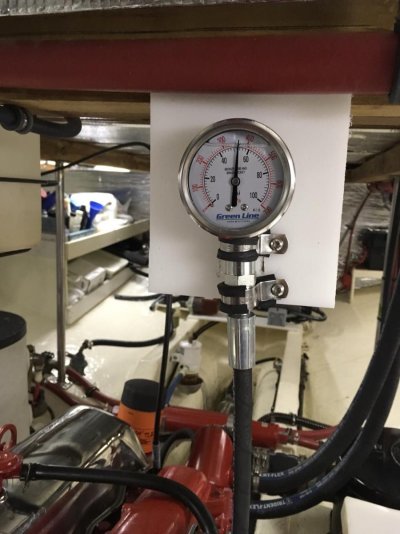
You can also put a manual gauge on in place of the sender to check the engine. Harbor Freight and Amazon have them cheap.

Most likely, it is a wiring problem. Less likely, a gauge or sender problem. At an unlikely extreme it could be a stuck oil pressure relief valve (if it doesn't come down when warmed up), or a blocked oil galley.

I'd make sure it is the monitoring not the engine before I'd run it too long. If a galley is blocked, as hugely, extremely unlikely as that is, something wouldn't be getting oil.
 
Last edited:
You can run a temporary wire from the sender to the gauge to confirm that it is a wiring issue. Just get a long wire and make the connection without trying to run it through the chases, etc. just run it over the deck and see what happens.
 
Different Oil Sender arrangement for my two Perkins

Thanks for the jumper wire idea to verify gauge and wiring functionality. I used that approach to trace the Low Oil Pressure Buzzer circuit on my port engine and found a loose wire.

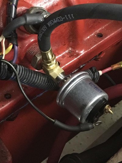
On the starboard engine, the oil pressure sender has a single connection. The Oil pressure switch has two connections: one wired to the engine block, the other daisy chained with a high water temp switch then to the buzzer,

On the port engine, the oil pressure sender appears to have two connections: one to the engine block, and one to the gauge, The oil pressure switch has one connection that is daisy chained to the high water temp switch and the buzzer.

Is this common, or am I missing something.

My low oil pressure buzzer on the port engine was not working because the double blade "daisy chain" connector came loose from the oil switch connection point.

When I touch the double blade connectors to ground the buzzer sounds off. But when I touch the connectors to the oil pressure switch single connection, I do not get a buzzer response. Because of the location of the oil pressure sender and oil pressure switch, it was very hard to get certain contact with the switch connection point.

The low oil pressure switch on the port engine is VERYYYYYY hard to get to. It is behind the seawater inlet hose and the many associated coolers. Tomorrow, I will try to get an ohm meter on the oil pressure senders and switches to verify whether they are working.

This process, along with the 25' jumper cable, should also tell me why the oil pressure gauges are pegged on both engines.

Perhaps I should just replace both of the senders on both engines and rewire them with new wire. It might actually be easier to take out the "T" with the two sensors attached and reinstall the new set of sensors with wiring attached prior to installation, than to get to to most difficult sensor connection points.

Your thoughts are appreciated.
 
Most senders and switches ground through the engine block. Some senders are "floating ground" and have a separate ground that can tie to the engine block or elsewhere. They can achieve the same thing either way. The separate wire can sometimes lead to a better or more consistent reference.

I wouldn't tighten down (or even attach) the wire on the sender or alarm switch before spinning it in, or the wire is likely to end up really kinked and twisted and the connection stressed.
 
Spinning in a new sensor

Good thinking.

I thought I would install the sender & switch to the "T", attach the wires, spin the "T" in, then run the wires to the target location, though, the wires might actually get in the way while spinning the "T" in:banghead:

But as you likely know, no human hand will fit behind the cooling system to connect/dis-connect a wire(s) to "which ever" sensor ends up behind the cooling system, once the "T" is installed. On one engine, the switch is inaccessible. On the other, the sender is inaccessible:banghead:

Another idea!

Perkins and VDO make combined sender-switch sensors, with 3 connections. That would get rid of my "Ts" and make the connections more accessible. The down side is, if the sensor or ground fails I lose both the low pressure switch and the oil pressure indication on the gauge. The Perkins sensor costs about $120. The VDO is a little less expensive, but I don't know if it is compatible with by gauge?

Is this a good idea, considering that both companies make quality stuff?
 
First troubleshooting question...

Has the oil pressure always been pegged?

This is important. Wires some loose, wires accidentially short, wires DO NOT get miswired on their own.

So... If this problem just occurred then the gauge is not miswired.

2nd, think about how a gauge works to troubleshoot.

All analog gauges measure current (even analog voltmeters) That is how the gauge movement works. Zero current and the gauge will stay at zero. increase the current and the needle moves. Maximize the current and needle moves to the 100% position.

So... Thinking about how a gauge works, if your gauge is pegged then either the sender is shorted, or the wire going to it has come loose and shorted to ground.

If your gauge reads zero then either the sender is open, or the wire has come loose.

If... it was working then quit working of course.
 
Last edited:
You have a dead short to ground somewhere.

pete
 
Kevin's comments above are totally on point.

As for the combined switches and senders, I don't know about the Perkins branded ones. I've used the VDO and they require a VDO sender with a "Wk" warning contact terminal. If you are replacing the sender and gauge(s) as a pair, that'll work fine. Just remember to order the dual station version if you have two helms.
 
Instruments not working on Port Engine

Thanks for your expertise.

Sorry for all of these words, but I am hoping my explanations will light a light or identify an error in my actions or thinking.

I have been looking for a ground to explain and correct my problem. But, wouldn't a ground "peg" more gauges than just the oil pressure gauge?

I verified the wires coming from each gauge to the upper helm terminal block were not grounded.

Then, I verified that the wiring for each instrument is good from the upper helm terminal block to the engine room terminal block that the sensors are connected to.

I found that the wire that is daisy chained from the engine room terminal block to the low oil pressure switch and high temp switch on the port engine was disconnected from a blade connector on the low oil pressure switch. When I grounded the disconnected wire, the buzzer sounded off. The blade connector on the low oil pressure switch was so "rusty" that I could not reconnect the wire. I tested the resistance between the "rusted" switch connector and the engine and got an open connection reading on the ohm meter. It sounds to me like the switch is bad, or the connector blade is so "rusty", I was not making a good connection.

Is a "rusted" steel blade connector typical on a marine sensor? I would have expected a copper blade connector.

I also found the transmission oil pressure wire had separated from the terminal block connector. Upon reconnection, the transmission oil pressure gauge jumps to the "0" reading when the ignition switch is turned on.

I found that every copper connection for all of these gauges and sensors was so corroded that I got constantly varying voltage and/or ohm readings when testing the connections. High resistance in the circuits might explain some of my problems.

I did not find a short - YET.

Tomorrow, I plan to remove the corrosion on every instrument wire connector then retest the quality of my connections from the upper helm to the sensors.

Any suggestion about how to get the connections back to "spec" would be appreciated. I plan to use CRC and a wire brush or sand paper. Some have suggested vinegar and salt, then soda.

When testing the voltage output from the water temp and oil pressure gauges, with the ignition switch on, I found between ~6 and ~9 volts at the terminal block in the upper helm and the same at the terminal block in the engine room. While conducting this test, the object wire was tested when disconnected from the terminal block and should not have been affected by downstream connections or sensors.

Is this what I should have seen coming from these gauges? The purple "instrument power" wire coming from the ignition switch, then daisy chained to each of the gauges, tested 13.4 volts.
 
Clean push-on connections very gently. Sand them much, at all, and they'll get thin and won't stay together. If there ianroom on the wire end, it is often worth trimming it back and putting on a fresh connector. On the device side, it is more of a judgement call, sometimes it is worth replacing. But, try cleaning, even chemically, before sanding. Also, apply a protective grease before reconnecting to keep moisture away. Dielectric grease is the common advice. For large connections not close to others, I sometimes use a conductive grease. Either keeps then moisure away.

When measuring voltage, you should see very close to the 12+v you see at the source the whole way. If it drops, it is likely a dirty connection. Sometimes the dirt is just on the outside, though, so it sometimes helps to get a better reading to scratch a little with the probe.

In any case, you want to fix connections so you arent dropping voltage along the way.

Let's be sure to distinguish your alarm switches, which are daisy chained and drive the alarm/light and/or sound from the senders, which drive the gauges, and are all at the end of a wire.

Senders usually vary resistance as the measured property, e.g. oil pressure, changes.

For oil pressure, no resistance, i.e. a direct shortage to ground via the engine block or ground wire (if 2+ wire sensor with floating ground), is often the highest oil pressure reading qnd, as pressure goes down, resistance goes up until 0psi.

You might try disconnecting the wire at the oil pressure sender, emulating very low oil pressure, and see what the gauge reads.
 
What brand gauges are installed? The main brands installed on marine engines are Teleflex/Sea Star and VDO. VDO senders work opposite the Teleflex senders, a least for oil pressure. Do not mix brands of gauge and sender!
 
I am getting ~6 to ~9 VDC on the oil pressure and engine temperature gauges at the terminal block in the upper helm, 18 inches from the instruments. I get 13.4 vdc on the purple wire that daisy chains to power all of the gauges. But, only the oil pressure gauge is pegged.

I'm cleaning and maybe replacing the push on connectors today, so we will see what happens.

I like the "switch the switches" idea, but removing the port low oil pressure switch is very difficult. I either have to remove the triple cooler - *!?% - or remove the oil pressure sender, turn the "T" 180 degrees then remove the switch. Then I would probably need to remove the "T" to clean it up and reseal it for reinstallation.

Because of the condition of the blade connector on the switch, I would probably replace it if I remove it.

This might actually be the best idea, even given the difficulty. I suspect normal maintenance has been seldom performed on this side of this engine because of the difficult access.

The 1/8" pipe connecting the "T" to the block looks like it has never been removed or cleaned.

Of course, this will all be done while laying my old body between the engine and the fuel tank. It only has about 13 inches and I use 12 of them:)

I'll check out the gauge brand today. I don't remember the VDO logo on the faces, but the previous owner has a couple of spare VDO instruments in the engine room storage.

If VDO, does that mean, poor connection and associated low voltage might peg the oil pressure instrument?

Thanks again for your help.
 
"I am getting ~6 to ~9 VDC on the oil pressure and engine temperature gauges at the terminal block in the upper helm, 18 inches from the instruments. I get 13.4 vdc on the purple wire that daisy chains to power all of the gauges."

Sounds like you are close to a potential problem. Check each of the connections and clean or replace the terminator it if needed, so that you get the same voltage on each side of the wire. If the wire strands are brittle and black, which is more likely in an anchor locker or bilge than inside a helm, but still possible, and you can't cut back to good wire, you may need to replace the wire, itself.

Sometimes you need to "scratch into" a connector or terminal a little bit with the meter probe to get a good reading. The outside is dirty and corroded, but where the parts come together is a tight squeeze, maybe even with an electrical lube on it, and has stayed clean.


"But, only the oil pressure gauge is pegged."

A few things on that. The way gauges are designed, they normally move by changing the balance of magnetic fields, so it is the difference across the sender that drives them, versus the absolute voltage. This makes them less sensitive to changes in voltage versus sender resistance (though there are limits). The second is, that, depending upon the gauge-sender pair, they may react differently, e.g. reading low or high, and by different amounts. And the third thing is that we don't know if the other gauges read correct or not, just that they aren't as extreme. I spent a lot of time cleaning connections to get mine to match my mechanical and IR instruments, for example.

Having said all of that, when a gauge is pegged at LOW or MAX, it is normally a problem in the extreme, a disconnect or short. If one can see the needle bounce at all when power is turned on to the gauge, it isn't a disconnect. And, "American Standard" oil gauges go to MAX when shorted ("VDO standard" does the opposite, but VDO makes some "American Standard" gauges, also).


"I'm cleaning and maybe replacing the push on connectors today, so we will see what happens."

Good idea!


"This might actually be the best idea, even given the difficulty. I suspect normal maintenance has been seldom performed on this side of this engine because of the difficult access."

Personally, I don't like neglecting gauges because they give me a lot of reassurance as I am using the boat.


"I'll check out the gauge brand today. I don't remember the VDO logo on the faces, but the previous owner has a couple of spare VDO instruments in the engine room storage."

I wouldn't make an assumptions based upon that. I, for example, have got some spare gauges on the boat -- I took them out to make both sides symmetric, and they are a different standard than the ones in use now.


"If VDO, does that mean, poor connection and associated low voltage might peg the oil pressure instrument?"

That's hard to say. VDO makes gauges and senders that match each of their own long-time standard, and what has now emerged as the "American standard".

I have attached a sheet that shows a resistance-pressure table for each of their gauge "movements", by movement number. You'll see for many types of gauges, they have products that support both standards.

I've also included a less detailed document from Faria, which shows some data points for "American Standard" gauges.
 

Attachments

  • PressureResistanceChartVDO.pdf
    716.3 KB · Views: 13
  • GaugesFariaHowToTest-IS0345a.pdf
    230.6 KB · Views: 6
Last edited:
You are (from your posts) mixing up several separate problems on several separate circuits and rolling them into one problem.

Each gauge is a separate circuit. The only interconnection of the gauges is that they all get 12Vdc from the key switch.

The alarm/buzzer circuit is separate from the gauges. This circuit works by feeding 12 volts from your key switch directly to the alarm/buzzer. The current path to ground, which makes the buzzer sound is completed by any of a number of sensors. Any of them in an "alarm" condition closes a switch in the sensor to ground again allowing current to flow which turns on the buzzer.
 
Thanks Kevin, I was wondering the same. The buzzer sounds as the circuit is grounded due to low pressure/no pressure at start.
IMO if the gauge pegs out the sender is shot as it is grounding fully 100% instead of progressively as pressure is applied. For lack of better words, the sender has a rheostat inside from no pressure to high = 0-100%.
There are two separate senders low and 0-100%, am i correct
 
Unless I'm mistaken, the trouble report here is just that the oil pressure gauge is pegged high. It is normal behavior for the low oil pressure (LOP) alarm to sound for a small few seconds after start until oil pressure comes up, at least in many boats.

Given this, the first question can be, is the sender bad. This is easy to address by checking it with an ohm meter while the engine is running and comparing the value for reasonableness to those in the table in the attachment I posted. For a more detailed check, one can compare to a mechanical gauge for correctness, nit just reasonableness. A very low reading (or possibly a very high reading), e.g. off scale, would point to the sender as the problem.

While the wire is disconnected, the gauge should be at one extreme. Touching it to the block should show the other extreme. This would prove the wiring.

One can also put a volt meter on the end of the wire and measure to see if the voltage from the gauge has dropped off.

In any case, if it isn't the sender, the wiring likely needs to be traced from the gauge to the distal end until the problem is found, maybe at a connector near other connectors or terminals, or chaffe point or a penetrating screw, etc.

Most likely it will be found to be shorted to ground. But, not knowing what type of gauge it is, it could also be a broken connection

There is also the outside chance it is the gauge. It can be tested by momentarily moving a pigtail from the sender terminal on the gauge from open to ground and watching the gauge for full movement. It can also be tested by putting a resistor with a value taken from the chart Inearlier attached in between that pigtail wire and ground and seeing if it reads according to the chart.

Ultimately, it is the gauge, the sender, or the wiring. The gauges and sender can be checked easily. The wiring is a linear search along the path, but maybe starting at the ends.
 
Last edited:
This is how I know it, single wire to sender, sender grounds to engine. If you have a two wire sender then the second one is low oil pressure. On mine I have one each

oil pressure sender.jpg
 
This is how I know it, single wire to sender, sender grounds to engine. If you have a two wire sender then the second one is low oil pressure. On mine I have one each

View attachment 118592

Could be. Or the 2nd wire could be a floating ground wire, which enables a better ground than through the engine block, or at least one more directly tied to the gauge ground.

It is a little uncommon, but less so with VDO, which was mentioned above and which sells a lot that way,
 
Last edited:
Thanks Kevin, I was wondering the same. The buzzer sounds as the circuit is grounded due to low pressure/no pressure at start.
IMO if the gauge pegs out the sender is shot as it is grounding fully 100% instead of progressively as pressure is applied. For lack of better words, the sender has a rheostat inside from no pressure to high = 0-100%.
There are two separate senders low and 0-100%, am i correct

correct!
 
My gauges are all VDO, probably circa 1979. I have two different low oil pressure switches and two different oil pressure senders. I will try to determine tomorrow if the sensors are all VDO.

I understand that all of the instruments have independent circuits.

I have determined that the buzzer wiring is good by grounding the wire that came loose from the low oil pressure switch. The buzzer sounds off!!! I will clean the rusted blade connector on the low oil pressure switch tomorrow and verify whether it is working using an ohm meter.

I will also clean all of the instrument connectors and replace any that have corroded wire-connector interfaces.

I still have not found a short.

I am bugged by the 6-8 vdc readings I am getting directly from the 18" long wires coming out of the bottom of the oil pressure and engine temperature instruments. These wires run in a bundle for about a foot.

I'm about ready to pull an instrument, take it apart, and test the voltage at the connector for the sender wire to see if it is 6-8 vdc at that point.

But, I won't do that until I have cleaned up all of the connections and verified whether the oil pressure sender and switch are working.
 
I'm not super bothered by the 6-8vdc that you are reporting, only because I don't know exactly how it is being measured or what is being measured -- and for many designs and situations that could be fine.

Different designs are certainly possible, but classically, these gauges work by using coils to generate a magnetic field to deflect the needle. Usually there are at least two opposing coils, one which pulls the needle one way and the other which pulls the needle the other way. They can be configured so the position of the needle depends upon how much current is shunted through the sender and away from one of the coils, or how much current passes through one coil, adjusted by the sender, as compared to how much current passes through the other coil via a reference resistor. They can also be configured with three coils, such that two coils are in balance, and a third coil is used to "buck" or oppose one of them, allowing the flow through the other coil, also as controlled by the resistor, to control how much. The key to any of these designs is that they are "balanced". In other words, there is a left pull and a right pull driven by the same voltage source, each across a calibrated coil, so that whatever the voltage is, it balances out and doesn't affect the reading, at least within reason. Too little and there won't be enough current to drive the electromagnets to move the needle, and too much and the current will be too high and something will burn.

Where I'm going with this is that, with the sender disconnected, if you measured a 2-coil gauge from 12v to sender, you are measuring the voltage drop across one but not across both coils. So, I'd expect it to be less than 12v. If you measured it with the sender connected, the sender and the 2nd coil would be in parallel, so you'd be measuring the voltage drop across the 1st coil, but not including that parallel load.

In a 3-coil gauge, with the sender disconnected, you'd be measuring the voltage drop across the low coil, but not also across the high and bucking coils. If the sender were connected, you'd be measuring the drop across the low coil, but not also across the parallel load of the bucking and high coils plus the sender.

In ay of the above configurations, we've got a voltage divider and you are measuring the drop across the left half of it, not all of it. If you'd want to measure all of it, you'd have to measure between 12v and ground -- which you did, and you know is correct.

If you were seeing the same thing 12v-to-gnd as you were seeing 12v-to-sender, that's when I'd be concerned. The only time I think you should see that is if the sender wire is grounded, e.g. the sender has a 0 resistance.

And, again, I don't actually know what gauges you have or how they work. I'm just suggesting that in most balanced gauges, sender wire voltage being different from ignition voltage would be a red herring, not diagnostic information.

I really encourage you to do some of the debugging I mentioned earlier:
-- What happens if you disconnect the sending wire at the sender?
-- What happens if you ground it?
-- Does the above generate two different extreme gauge readings?
-- What about if the sender wire is grounded and opened right at the gauge (versus at the sender)?
-- If you have a resistor that is somewhere in the middle of the gauge range, what happens if you disconnect the gauge sender wire, wire it to ground through that resistor, and turn on the power? Does it read mid-way?
-- With the engine off and the wire disconnected from the sender, how many ohms do you read from the sender to ground? What about with the engine running normally? How do these look compared to the values in the table I posted?
-- With everything powered off, how many ohms do you read between the gauges ground wire and another known-good electrical ground?
-- With the sender wire disconnected at the sender and at the gauge and everything powered off, how many ohms do you read gauge-side sender wire to ground? To 12v?
-- What if you do the above at the sender side?
-- With the sender wire disconnected on both sides and everything powered on, how many volts do you read to each of 12v and ground? Measure on both sides.
-- With everything hooked up and powered up, how many volts do you read to ground at the back of the gauge sender wire terminal? What about at the other end of that wire where it meets the sender?

The goal here is to find the gauge not moving from one extreme to another, and, if you can test it, being able to sit in between (though this would be a weird failure case); to to find the sender failing to have the proper resistance at 0ps and/or failing to change resistance as oil pressure changes; to find the sender wire shorted to ground; to find the sender wire shorted to 12v; to be able to find the sender wire having a low-resistance path to either; or finding the sender wire, itself, has high resistance from end-to-end.
 
While you are working through this, consider installing a mechanical oil pressure gauge and mounting it above the engine. A “T”, some hose and a pressure gauge are all that is required. I did this when I replaced my “two-station” sender gauge and it gives piece of mind that the two match. Cheap and easy peasy! Even a biologist can do it.

Jim

IMG_3247.jpg

IMG_3255.jpg
 
instruments pegged prior to start & warning buzzer doesn't work

OOOOK!

I cleaned up all of the instrument connections from the upper helm to the port engine.

I tested ~8 volts at the sender connection on the bottom of the transmission pressure gauge - after I discovered both the purple, hot wire, and white, ground wire, were disconnected.

I tested 6-8 volts at the sender connections on the oil pressure and water temperature gauges.

I cleaned up the low oil pressure switch on the port engine. The blade connector was in fact copper or bronze. When I touched the buzzer warning wire to the body of the switch, the buzzer sounded off. When I touched the wire to the blade connector - nothing happened.

I pulled the sender, switch, "T", & 1/8 NPT pipe out. I tested the resistance from the body of the switch to the blade connector and got a bunch of resistance, and no direct connection. This switch grounds through the body of the switch, so, I think the switch is bad.

I will talk to VDO tomorrow to learn if their V360006, oil sender/switch combo can activate a 3" mechanical buzzer. Their marketing literature says it will activate an idiot light. I am hoping it will handle the buzzer, so I can simply screw in the dual sensor and hook it up with new connectors.

When I turn on the switch for the port engine, the gauges now act exactly like the starboard engine gauges. Three of them PEG and the transmission gauge moves to the "0" position. Once the engine is running, the starboard engine registers believable readings.

Once I reinstall the VDO sensors (and replace a leaking port transmission oil cooler), I will start it up and see if the instruments are now working.

I am starting to suspect that the normal operation of the 1979 era VDO instruments is to move to the peg position until the engine starts.

We will see. I have found no shorts or grounds.

RE: the engine room gauge suggestion. I plan to move all of the instruments to the engine room and send a video to the helm as a backup, after I install some kind of NMEA 2000 condition monitoring system that will display engine condition and alarm anomalies.

And, WOW, what a beautiful engine room you maintain. That is my goal, but I am just getting started.

Thanks for all of your help. I will update you about Wednesday of next week.
 
By memory, the switch associated with the Wk terminal on so-equipped VDO gauges is rated for 5W non-inductive loads.

That can easily support an appropriate LED warning light and an appropriate piezo buzzer. But, that may not be enough to support an incandescent warning light and/or electro-mechanical buzzer. And, even some LED and/or piezo combinations could go over 5W. So, you'll want to check my memory against the specs listed for the sender as well as check or measure the specs for whatever alarms you want it to switch.

I just sent you a PM. If you want, give me a call tomorrow. I think a bunch of things might be getting conflated, making this harder for you to sort out than need be. I think I may be able to talk you through it faster than via posts.

The oil pressure /switch/ should test near 0-ohms when the engine is off, because when the engine is off, the oil pressure is 0. So, the switch should be in the alarm state -- able to ground the alarm, providing a current path, causing it to activate.

We need to be careful to distinguish the behavior of the /senders/ for the gauges and the /switches/ for the alarms. They work differently.
 

Latest posts

Back
Top Bottom