Debugging a parallel battery switch

The friendliest place on the web for anyone who enjoys boating.
If you have answers, please help by responding to the unanswered posts.

The Brockerts

Senior Member
Joined
Oct 17, 2014
Messages
246
Location
USA
Vessel Name
Moonstruck
Vessel Make
1990 Californian/Carver 48 MY
Looking for some guidance debugging(testing) a parallel Battery switch.

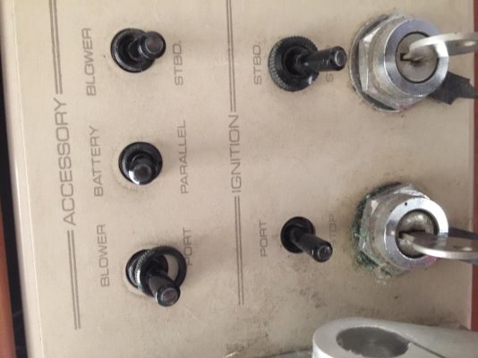
I've got twin 3208 Cats, 2 8D starting batteries per engine. I've got a Parallel Battery switch(see picture) at the helm. As I'm testing and fixing all electrical issues, I've come across this and I'm struggling with the testing/debugging.

So disconnect the Port 8D batteries, flip the parallel switch and see if the port engine starts off the STBD 8D's? Seems that might be a valid test.

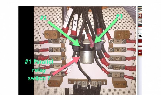
Seems like there is a DPDT electrical switch in my 12c DC panel.(see picture).
If I flip the switch should I hear that relay throw?

Seems like I should be able to measure 12v DC somewhere on that switch when the parallel helm switch is thrown.

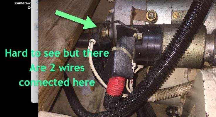
I'm also puzzled by the starter battery cables. 2 cables are connected to the starter, One for each bank?

I'm looking for some ideas on the best way to test all of this

The Brockerts
 

Attachments

  • starterwiresTF.jpg
    starterwiresTF.jpg
    108.9 KB · Views: 42
  • 12vpanelTF.jpg
    12vpanelTF.jpg
    126.4 KB · Views: 44
  • parallelswitchTF.jpg
    parallelswitchTF.jpg
    87.9 KB · Views: 28
Most I have fooled with used a SPDT switch, so the parallel solenoid could be powered from either bank. That way if one bank is totally flat, you could swap switch direction and power it with the good bank.

Best way to sort this is to follow the cables and make a schematic of the whole system.
 
I can't quite see the two wires on the starter. Approximately what gauge are they, e.g. small enough to power only the solenoid or big enough to power the motor?

How many helms do you have?

With the switch normal, try disconnecting one battery from ground and starting the corresponding engine. It shouldn't work. Try starting the other engine, it should. Flip the switch to parallel and both engines should start. Restore the ground and repeat the three experiments for the other battery.

Cheers!
-Greg
 
The contact noted 2 wires appears to be to activate the solenoid. The primary 12V cables are much larger (2/0 or 4/0?) And appear to be well marked with red wrap at the terminals. Possibly from upper & lower helm?
 
See If I can get all the questions answered and then add a few more questions and pictures

Yes I have 2 helms, upper and lower(inside) and both have the parallel switch.

The 2 wires on the back of the starter are 4/0

The switch seems to be a momentary possibly SPDT. I can toggle it up or down.
It doesn’t not stay in either position. Shouldn’t it click into either up or down position or is it designed to be held UP/DOWN while turning the key to start?

While holding the switch up or down I can not measure any voltage on the solenoid labeled #2 and #3 in the picture and I can’t hear and click or anything.

I’ve added some pictures of back of the switch.

I’ve tested the helm switch and it failed. It has GND and power but when toggled and held down or up it does not transfer the 12vdc. It has an up position and down(both momentary), but appears to only have contact/lugs for one way with both wires attached to the same lug.

So I’m replacing that switch, question is should it toggle on/off or be momentary ?

The Brockert
 

Attachments

  • switch2TF.jpg
    switch2TF.jpg
    89.1 KB · Views: 17
  • switch1TF.jpg
    switch1TF.jpg
    116.1 KB · Views: 15
Easy stuff first. Your post #5 seems to indicate that both the upper and lower helm switches are bad. Have you confirmed that you have B+ at the line side of the two switches? If so, then per your discussion, they have failed.

Regarding SPDT, SPST, Momentary, etc.: I think that the replacement switch should be a momentary SPST (ON)-OFF. Momentary because the paralleling line-up is only required while cranking the engine with a bad battery.

Now to the solenoid/contactor. Disconnect the small activating wires (B+ and B-) from the solenoid. Use a jumper and connect one of the small studs to B-. Use another jumper from a verified source of full B+ and touch the other small stud. If the soenoid fires you will hear it and it is ok.
 
A multimeter would help with the diagnosis. Do you have voltage to the toggle switch? Do you have voltage out of the toggle switched when turned on? Or just continuity through the switch.
So 4-8D's to start 2-3208's, that'll do it.
 
Ok, started a re-test of everything I'm doing after I notice some mistakes in my testing. Here's where I'm at.

The solenoid/contactor works. I’ve jumped power to the positive side and you can hear the solenoid hit. I still need to test that once the solenoid goes that both batteries are connected but the sound was solid.

Switches. The lower helm is very hard to get to and getting a meter on the back will require a lot of hard work, I.e. disassembly of steering and hydraulics.

Upper helm switch. I can get to it and got a meter on it. The switch in the pictures are incorrect. The switch is a DPDT with only one side being used. This switch tests good on a meter. The problem is there is no power to it.

I’ve got the boat setup to start and it does. Ignition breakers are on. I’ve turned every breaker on, on the panel and there is still no power on the switch.

I’ve started tracing the power line and this will take time as it’s in a bundle, then down a wall, then across the boat. I’ve not found the end yet. As I tear apart the boat the admiral is asking a lot of questions.

So, what conditions might there be before power to this switch might exist? Would there be any conditions, like ignition breakers on ? (there on),
What might the breaker be labeled as ?
How about an inline fuse? In a wall somewhere?
What “other” switch might need to be on first?

I’ll continue to trace this line down, cutting as few holes as I can.

The Brockerts
 
It seems like you are carrying a lot of battery power for engine start. I have the same cat 3208TA's and use a single 215 amp agm battery for both engines. I can connect the house bank (5 215amp agm's if needed for start assistance. The single battery starts the engine within a 1 or 2 seconds of turning the switch with a cold engine. Maybe you should rethink the house bank and engine start battery wiring design.
 
Im trying to figure why there is a ground on the parallel toggle switch. Why switch a hot to ground? So my mental picture of the circuit does not compute.
My thoughts are to have two good start batteries and there will be no need ever for the parallel network.
 
So you are using one side of a DPDT. That is fine. One outer terminal should have power from port ign breaker, the other outer terminal should be fed from the stbd ign breaker. The center terminal should go down to the ER and feed one solenoid coil terminal. The second coil terminal should go to 12v neg buss somewhere. No need for power supply to course all the way into the bundle, power should be a short hop inside panel going to say the pos terminal of start button or ign sw.
 
Current state: Yes 4 8Ds to start 2 3208’s is a lot of battery. That’s why I’m debugging the parallel switch setup as I will be going to a single 8D for each engine and the other 8D’s (or it space) for a house bank. I want the parallel switch working to be able to easily grab the other 8D for starting.

The GND on the switch is for the light in the toggle lever.

Ski in NC is right on with the setup for the upper helm. So I turn the ignition to on for the port engine, toggle the parallel switch up, and the solenoid fires. Toggle down, nothing happens. On the STBD side, ignition to on position, toggle the parallel switch up or down, nothing happens.

Seems interesting that both the upper and lower helm STBD side does not work while the port side works in both helms.

I’ll pull that switch out in the next few days and test it with a meter.

Now that I understand how it’s to work debugging should be easier.

The Brockerts
 
Normally the power to activate the solenoid is coming from the house battery (s). That way you do not have to worry about which battery is good enough to energize it.
Note the location of the Solenoid on a panel with a fuses used for the house.
Good luck,
 
Thanks everyone that chimed in. Got this basically working. I've got 2 switches that need replaced as they are working on one side but not the other.

On to the next project.

The Brockerts
 

Latest posts

Back
Top Bottom