kernr
Senior Member
- Joined
- May 29, 2020
- Messages
- 144
- Location
- United States
- Vessel Name
- Serenity
- Vessel Make
- Grand Banks 47 Europa
Hi All -
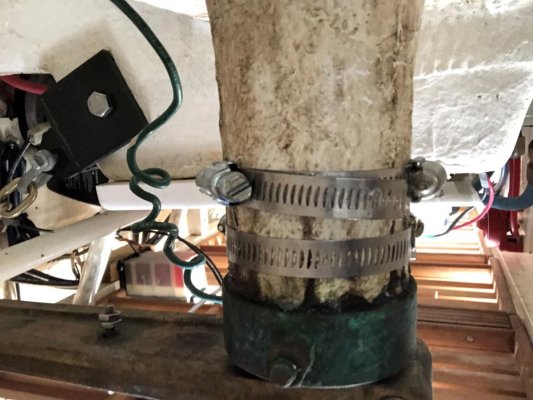
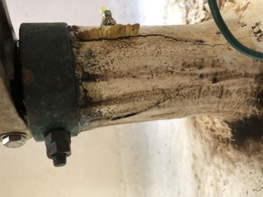
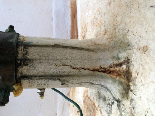
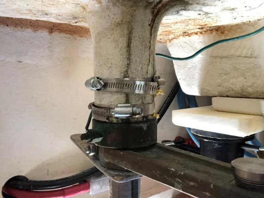
Well I have learned a lot about our GB 47 EU over the past year. One item that I have not checked out though is our rudder posts. A couple of times last year at the higher speeds I noticed water in the bilge of the Lazerette (sp) and I saw the bige pump light come on once or twice while underway. Never an alarming amount of water and never have I observed leakage source while in port or while underway. On this particular boat it seems like the mechanism that secures the rudder posts to the boat is above the waterline except possibly in rough seas or when she is squatting down in the rear. Just never got there at the time it was happening. I have spotted water on the flat surface next to the Starboard post and tried to see any evidence as to its source. So I am guessing I need to look at the packing.
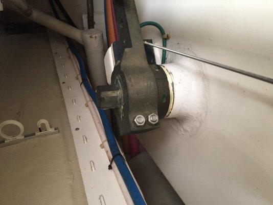
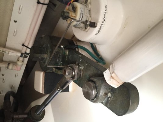
She is on the hard now for about another month and would like any advice as to what needs to get done. Pictures of the port and starboard post are attached. Below the flat surface you see in photos is just fiberglass surrounding the tube that the post comes thru. So where do I start to examine the situation? Do I have it correct to say the packing is most likely under the top bracket with the two bolts clamping it in place and the lower collar is what is securing the rudder post to the top of the tube?
Bob
Well I have learned a lot about our GB 47 EU over the past year. One item that I have not checked out though is our rudder posts. A couple of times last year at the higher speeds I noticed water in the bilge of the Lazerette (sp) and I saw the bige pump light come on once or twice while underway. Never an alarming amount of water and never have I observed leakage source while in port or while underway. On this particular boat it seems like the mechanism that secures the rudder posts to the boat is above the waterline except possibly in rough seas or when she is squatting down in the rear. Just never got there at the time it was happening. I have spotted water on the flat surface next to the Starboard post and tried to see any evidence as to its source. So I am guessing I need to look at the packing.
She is on the hard now for about another month and would like any advice as to what needs to get done. Pictures of the port and starboard post are attached. Below the flat surface you see in photos is just fiberglass surrounding the tube that the post comes thru. So where do I start to examine the situation? Do I have it correct to say the packing is most likely under the top bracket with the two bolts clamping it in place and the lower collar is what is securing the rudder post to the top of the tube?
Bob