Transmission removal

The friendliest place on the web for anyone who enjoys boating.
If you have answers, please help by responding to the unanswered posts.
Joined
Oct 7, 2007
Messages
3,146
Location
USA
Vessel Name
Apache II
Vessel Make
1974 Donald Jones
Refering to a starter issue that I had in the Diagnosis game.
I now need to pull the transmission to replace a damaged coupling on the back of the fly wheel.
I have several issues I need to address.
one is that my engine is hard mounted to the stringers. No rubber motor mounts.
The rear mounts are on the transmission housing. So I will need to block the back of the engine to facilitate the removal.
This will require sliding the shaft back enough to unbolt the tranny housing.
Anyone have any experience doing this?
Do I need to do anything special to the stuffing box or will The shaft just slide back to the rudder post. I am going to attempt this while still in the water.
This is on a Cat 3208 N.A. with a Twin Disc Marine gear.97 to 1 reduction
Any advice or experience would be appreciated.

Sd
 
Last edited:
SD, Every boat is different but I have done this dozens of times. If you have a traditional stuffing box, you can just slide the shaft as far aft as it will go until it hits the rudder. You should be able to unbolt the transmission and slide it back until the spine is clear. As you said, you will need to block the aft end of the engine. I don't know that I have ever seen a boat with no mounts and bolted directly to the stringers. The vibration must be something special. We are actually about to pull ours for a thorough check and seal replacement. We have a dripless system but don't anticipate any problems since I have done this before also. Not a big deal. Depending on your hours you might consider replacing the damper plate while the transmission is out. Be sure and realign the shaft after everything is back in. Chuck
 
When our local diesel shop replaced the worn-out enine mounts on our FL120s about eight years ago they used a tool called a PortaPower to lift and support the engines while the mounts were being changed. Actually they used several of them. Ironically I have a PortaPower which is a manually operated hydraulic cylinder to which all sorts of attachments, clamps, bases, etc. can be fastened. You can use it to spread things apart or squeeze them together. But I didn't have the time or the experience to try to tackle the job myself.

They also had various wooden braces they've made up over the years to spread the load on an engine that is being lifted by one or more PortaPowers.

I've heard of other methods of lifting an engine in a boat, from airbags to bottle jacks. But the shop we use seems to like the PortaPower, at least at that time.

A nice trick which you probably know about since it's used on vehicles, too, is to have a pair of log rods the same diameter as the transmission fasteners and threaded the same on one end. Take out a fastener on each side of the transmission and replace them with the rods. Then when you remove the rest of the transmission fasteners it will remain in place and you can slide it back on the rods to remove it. The rods also help in remounting the transmission as you can use them as guides to position and hold the transmission in place while you install the rest of the fasteners.
 
Last edited:
SD, Every boat is different but I have done this dozens of times. If you have a traditional stuffing box, you can just slide the shaft as far aft as it will go until it hits the rudder. You should be able to unbolt the transmission and slide it back until the spine is clear. As you said, you will need to block the aft end of the engine. I don't know that I have ever seen a boat with no mounts and bolted directly to the stringers. The vibration must be something special. We are actually about to pull ours for a thorough check and seal replacement. We have a dripless system but don't anticipate any problems since I have done this before also. Not a big deal. Depending on your hours you might consider replacing the damper plate while the transmission is out. Be sure and realign the shaft after everything is back in. Chuck

Yeah the hard mount thing is different but on past threads this was discussed. It seems common on older Commercial fish boats.
question on the damper plate. I am not sure where this is. I will check with Cat and Twin Disc to see if it is a wear item. Thanks for the tip.

As to realigning the shaft. Is this a procedure requiring a specialized approach with special tools and measurements? Once again I am unfamiliar with the procedure.

SD

My damper is a red urethane disk about an inch thick directly behind the tranny's output.

Realigning the shaft is an art form. about the only special tools you need are a good set of long feeler gauges and a truckload of patience. :) Not looking forward to the day I have to do ours.
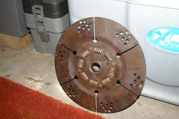
Tom-
 
A nice trick which you probably know about since it's used on vehicles, too, is to have a pair of log rods the same diameter as the transmission fasteners and threaded the same on one end. Take out a fastener on each side of the transmission and replace them with the rods. Then when you remove the rest of the transmission fasteners it will remain in place and you can slide it back on the rods to remove it. The rods also help in remounting the transmission as you can use them as guides to position and hold the transmission in place while you install the rest of the fasteners.

Marin, A new one on me. Not quite sure I understand the method you are perscribing It sounds like something I will have to see. I have a pretty good automotive mechanic that will be guiding me along on this. Perhaps he will know of which you speak.

Sd
 
A couple of lengths of "all thread" do the job nicely. They are, in effect, just longer bolts that allow you to line everything up while the parts are still far enough apart to see what is going on and slide into place over the threads until you can get the first couple of real bolts started.

It stops the heavy transmission from moving around while you try to hold it in place with one hand and put a bolt in with the other, or try to remove the last bolt that is holding all the weight.
 
I think I understand what you are saying. I will have to wait untill I really get into it. to fully understand.
I think the hard mounts are bolted to the transmission housing.
If I can remove the transmission without removing the housing it should be a bit easyer. Damm I need a light bulb to insert here. if I just unbolt the tranny from the housing I now understand the rods or as you say all thread. I need to fing out how much this marine gear weighs,.

As to the realignment. My engine is mounted midships with a shaft log that extends about 10 feet from the stuffing box to where it exits the hull at the shaft seal. I am thinking the with a shaft log that long the alignment should remain the same. ???

SD
 
...The rear mounts are on the transmission housing. So I will need to block the back of the engine to facilitate the removal.
This will require sliding the shaft back enough to unbolt the tranny housing.
Anyone have any experience doing this?
Do I need to do anything special to the stuffing box or will The shaft just slide back to the rudder post. I am going to attempt this while still in the water...Sd

On our last boat, the rear mounts were on the transmission. We unbolted the coupler and slid the shaft back 4 or 5 inches (we had a traditional stuffing box). I borrowed a hydraulic scissors jack. With the jack and a several pieces of wood at the rear of the engine just forward of transmission, we took the pressure off the rear mounts and unbolted them. Make sure if you do this method that you distribute the weight of the engine on as large a foot print as you can. That engine weights a lot!

We then set a tripod in the cabin sole and used a com-along to support the transmission as we slid it back. The com-along was then used to get the transmission out of the engine room. After we put the transmission back and reconnected the shaft we waited several day for everything to settle in and then did the engine/shaft alignment. To help with the alignment, scribe the 2 pieces of the couple before you take it apart. This hopefully, will make the final alignment go a little easier. Calder has a good write up in his book on doing the actual alignment.
 
Last edited:
On the back of the fly wheel is an aluminus disk called a transmission coupler
over the years the aluminum bolted to the steel fly wheel (Dissimilar metals)
coroded. Pieces of the aluminum plate had broken off. A chunk of this had managed to somehow lodge in the nose cone of the starter. The aluminum chunk would wedge and prevent the gear from engaging the flywheel.
When this happened I would use a screw driver to arc the positive and negetave contacts on the back of the starter solinoid.
This would generally force the Aluminus shard to dislodge and allow the starter to function, untill the next time it became wedged again.
That was why sometimes the starter would work and sometimes not.
by looking into the hole where the starter fits I could see the coupler and the places where it had disiegerated.

I have been experiencing a vibration between 1400 rpm's and about 1700 rpm's
I wonder if pieces missing from the transmission coupler could contribute to the vibration.

SD
 
Greetings,
Mr. Gonzo. I think the damper plate is internal in the transmission. Those orange do-dads, I think, are a "weak link" designed to break in case your prop comes to an abrupt stop whilst in gear rather than bending your shaft or destroying your prop beyond all recognition. As in "Dagnabbit, where'd that shoal come from?"
Agree on the all thread. IF or WHEN I ever have to remove my transmission, that's the first thing I will get.
I've got bread rising or I'd run down and look in the transmission manual.
 
A friend of mine raised his engine for service by putting 2X8 or 2X10 lumber on jack stands on the deck and raising it with come alongs under the engine instead of jacking it from below.

This may be an option, depending on access.
 
A friend of mine raised his engine for service by putting 2X8 or 2X10 lumber on jack stands on the deck and raising it with come alongs under the engine instead of jacking it from below.

This may be an option, depending on access.

The improvement on stability to this approach I used when placing new mounts under my 3208s was.... I used 4x6s across the engine hatch and long threaded eyes to shackles and chain to the engine.

A little grease on the threads and I raised the engines with one finger and a long box wtench.:D
 
The tranny is 250 # I'm gonna need some sort of lifting device and perhaps a little Euclidean geometry.

Sd
 
I had to release the pressure from the packing follower to back away the prop shaft from the transmission.
 
Damper plate from my Ford Lehman 120. It is bolted to the flywheel. The tranny shaft gets inserted thru the center splined hole
 

Attachments

  • Damper (Small).JPG
    Damper (Small).JPG
    48.6 KB · Views: 294
Mine is called a coupler and is made of aluminum. the tranny has rubber gromets or rubber blocks of some sort. It is hard to tell by looking at a cutaway of the Twin Disc. I think they do the same thing. When I pull it off I will know more.

Sd
 
skipper dude, I just removed my transmission last week. Your in luck. The first thing I did was look at it long and hard and drank a few beers before I did anything. Here is what I did that worked great.
1. I have 6-71's and there are two bolt holes in the back of the motor for a rear motor mount. Mine like yours is mounted in the front and the transmission. I got a fab shop to build two plates in an L shape with the bolt holes for the motor 3" o.c. and two 3/4" holes going to the bottom of the L. I bought a large diameter bolt with several washers and threaded the nut till' it forced the makeshift motor mount up. This took the weight off of the rear mounts and it is still holding today.
2. Keep all the shims and steel plates that are under the rear mounts so you can replace them exactly like they were.
3. I placed a 6x6 though two windows and fastened a chain fall to do the heavy. Don't mess around with a comalong because you cant control it enough to get everything aligned..
4. Take your trans. off and take the flywheel off and check your rear seal while your at it.
5. Now would be a good time to get everything serviced while it's out.
If you want pictures I will take them tomorrow. If anything I did can help.
Paul
 
We needed to remove our Twin Disc MG90990 transmission for a major service (mind you, you need to remove it for any type of service!!) last Fall. As with yours, the transmission housing included the rear engine mounts. We raised the engine up with a 2"x 6" using a bottle jack (Harbor Freight) and blocking as we went. Biggest challenge was barely having enough engine room height. Necessitated removing the exhaust riser and other parts just to get enough clearance. Once the transmission was separated from the prop. shaft, we pushed the shaft out of the boat - we have a dripless system- to get enough clearance to remove the tranny. Not sure I would plan to do this in the water - pretty sure it would not work on our boat. This is definitely a job for two people. Manhandling the tranny in/out of position was pretty awkward - ours weighs about 200lb. We began the project to deal with a leaking transmission seal. It turned out the clutch plates were fried (no obvious symptoms) and clutch parts had damaged the seal and the bearings. $3.5K later we have a rebuilt, as new, transmission installed.
Also, take the opportunity with the transmission out to replace the rear engine seal. It is pretty easy on our Cummins with the transmission removed. You certainly would not want to do this job twice if/when that starts leaking!! Best of luck with your project.
Chris
 
SD-- whenever you remove and replace any component of the drivetrain-- engine, transmission, shaft, cutless bearing(s)-- the engine-propshaft alignment must be checked and corrected. We're talking fractions of an inch here. IIRC the yard we use and our diesel shop use an allowable misalignment of one ten thousandth of an inch. Anything more than that and they say it must be corrected out by adjusting the motor mounts to bring the alignment back to no more than one ten thousandth of an inch.

The alignment is checked by separating the two halves of the shaft coupler and measuring the gap around the circumference of the coupler with a feeler gauge. The engine mounts are then adjusted to tilt or yaw the engine relative to the shaft until the gap is the same measurement all the way around.

As was said previously, while it is a mechanically simple process, adjusting the engine mouts for proper alignment is something of an art form.

The penalties for running with an out-of-alignment drive train are shaft vibration at best and shaft bending and premature wear on things like cutless bearings at worst.
 
Last edited:
IIRC the yard we use and our diesel shop use an allowable misalignment of one ten thousandth of an inch
I don't think that is the correct figure.
The "rule of thumb" is one thousandthof an inch (.001") per inch of diameter of the coupling. Hence a 4 inch diam coupling would be aligned within .004"maximum.
I was able to get mine to about .002"

One ten thousandth (.0001") would be impossibleto measure with feeler gages.

I'm sure you are correct. We had a new shaft and bearings put in the boat several years ago so it's been awhile since the topic was discussed. One ten thousandth does seem like an extreme measurement given the components we're talking about here.
 
Yes, I agree with jleonard. We adjusted to 0.004inch on the hard. Now we need to do the same after the boat has been in the water for a couple of weeks. Another job for 2 people. Amazing how many boat jobs need very long arms!!
Chris
 
The improvement on stability to this approach I used when placing new mounts under my 3208s was.... I used 4x6s across the engine hatch and long threaded eyes to shackles and chain to the engine.

A little grease on the threads and I raised the engines with one finger and a long box wtench.:D

This is a great idea I think it will be the one I use to raise the tranny.

Perfect control as I can raise it slowly a thread at a time.
Perfect Thanks.

Sd
 
This is a great idea I think it will be the one I use to raise the tranny.

Perfect control as I can raise it slowly a thread at a time.
Perfect Thanks.

Sd

I wasn't positive it would work as well as it did...2500 pounds hanging and yet up and down with a little side movement was onlt a fingertip in the box wrench...way cool...:D

I was more worried about the floor after I got setup rather than my rig...:thumb:

I did get the 18 inch long forged eye bolts (the kind used in building floating docks)...they were rated at over 2000 apiece and they were nice enough I figured I'd find some use for them after the project. Don't forget big washers as they help turn the nuts...:facepalm:
 
Yup,
As I am only lifting about 225# I will use a 4"X4".
I am not sure what model tranny I have so I will check the tag this weekend and then I can buy the part and be ready to go next weekend.
Chrisjs mentioned the rear seal. How much trouble is it to replace that.
I think I do have a leak there.
Anyone replaced the rear seal on a 3208?

Sd
 
You are correct on the use of a Come-Along. I used one and had to keep climbing in and out of the engine room to get the trans properly lined up ( I was working alone)on the re-install part of the job. Could not use the windows as the aluminum frames would have collapsed. I used a "Little Giant" aluminum ladder as an "A" frame and it worked just fine.
 
I used all-thread and a timber as well. Worked great.
I did block the floor from below to take some of the strain.
The one problem I ran into is that the rudder kept the shaft from sliding far enough to alllow the tranny to be removed. I ended up lifting the back of the engine 4" or so to clear the shaft. Of course this required a complete re-alignment after the rebuilt trans. was in place.
 

Attachments

  • Photo_013107_009[1].jpg
    Photo_013107_009[1].jpg
    96.1 KB · Views: 133
Back
Top Bottom