GoneFarrell
Guru
Bkay,
Yes, you got right. And it is an example of MPPT efficiency, about a 4% loss through the controller.
Yes, you got right. And it is an example of MPPT efficiency, about a 4% loss through the controller.
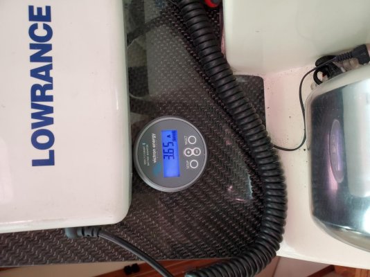
Okay, so the victron app that shows battery IS NOT the battery's voltage. It is the voltage that is being sent to the battery. I took these pics because I was confused why I'm getting different voltage.Here's how I have interpreted that - tell me if I'm mistaken here...
The panels are producing 87 watts. Divide that by 39.22 volts to get 2.2 amps. produced by the solar panels.
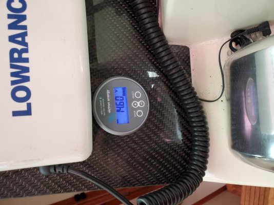
The batteries are in bulk mode and the controller is sending 13.24 volts to the battery. So the same 87 watts divided by 13.24 volts is 6.57 amps.
The difference between 6.57 amps and the 6.3 amps the controller is actually sending to your batteries is accounted for by some inefficiency or the power to run the controller. Is that more or less right?


So is there a way to get the Mastervolt to see what the victron is putting in? Run it through the shunt?SOC meters work by measuring the amount of current flowing into a battery bank and the amount of current flowing out. It does that by placing a shunt (small resistor) in series with one of the wires going to the battery and measuring the voltage drop across it.. (Typically the negative wire.) If when you installed the Victron controller you bypassed the shunt and connected it directly to the battery bank then the MasterVolt SOC would not see any of the current coming from your solar panels. The MasterVolt would see the voltage across the battery bank though.
Looks like I just need to move everything off neg post to the shunt.
Thanks for you explanation about the shunt.

That should work fine.
I am in the process of replacing my house bank and am going with a Balmar Sg200 SOC meter. It has some really good reviews so time will tell.