Perkins 6.354 electrical diagram

The friendliest place on the web for anyone who enjoys boating.
If you have answers, please help by responding to the unanswered posts.

DHeckrotte

Guru
Joined
Nov 1, 2015
Messages
1,024
Location
USA
Vessel Name
Revel
Vessel Make
1984 Fu Hwa 39
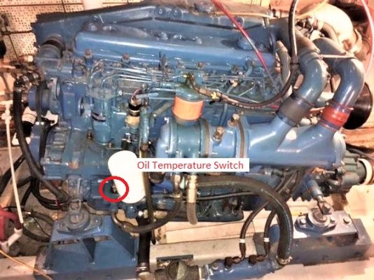
Thoroughly frustrated by our port engine and its apparent electrical woes. I've replaced the ignition switch, all three relays, and the starter solenoid.

No joy!

Turn key and the idiot lights light and alarms sound. Turn key to start and lights and sounds turn off and the starter gives one clunk and then nothing. (The starboard engine's idiot lights and sounds work until the engine starts.)

The engine will start if I turn the key to 'run', short the battery connection on the starter solenoid to the signal wire from the ignition (relay?). But the gauges don't work; the stop solenoid won't work; and the idiot lights remain off.

Conclude that there's nothing wrong with the starter motor or the starter solenoid.

I cannot find a circuit diagram that lays out how all those relays are supposed to work.
 
Okay... so this may or may not help. In our last boat we had a similar problem. Maybe the exact same problem. At the end of the day, I felt the need to go thru the entire of the motor's harness and make sure it wouldn't leave me stranded. Relays are easy to understand with the right teacher and grasp of their prime intention - To use a little power to turn on (or off) a lot of power.

However, I won't assume what your level of knowledge is on the standard relay, however, it is one of a number of systems many people overlook until they have to. So maybe that time for you is now. Or just maybe, you are in full understanding and have reached an impasse and it is time to beat the bush of knowledge... Trawler Forum. Either way... when face with the same issue, here is my solution. This thread really doesn't show much... just the final solution, however, I hope that it will maybe send you down the rabbit hole to getting you going again.

Good luck!

http://www.trawlerforum.com/forums/s4/little-relay-project-10094.html
 
I have solved a lot of electrical issues on my Perkins by cleaning and tightening all the ground wires.
 
Tom B, your 'as was' picture is exactly as mine look! Except that my engines are red and sport their original paint.

While I am a retired architect, I have some skills and knowledge of simple electrics (none whatever of electronics). I've wired two houses and done much successful troubleshooting and rewiring of several cars.

Gord May's diagram from 1977 is only a little helpful since it shows only one of the three relays and shows only a three position ignition switch (we have four position switches but no heater anyway). It's wire colors are fanciful as well.

Beating the bush of knowledge here is always fruitful!
 
Try joining the Mainship yahoo user group.

Even though you don't have one the perkins is the most common engine installed and there's tons of info in the "files" section of the user group.
 
Ok, so it's not a starter or solenoid problem then, more likely an electrical issue at your panel than a Perkins engine problem.

You're saying your panel instruments go away when you turn on the start key. This is a sign of a broken cable or poor electrical contact/connection somewhere between your B+ and the panel or ground. Turning the ignition key on is drawing more amperage than your panel can deliver.

A couple of thoughts:
Does your boat use the Perkins wiring harness? If so there will be several multi-connector rubber gang plugs where all the engine wiring comes together. One in front of each engine and usually under the instrument panel one for each engine and if you have a second steering station, one there as well. These connector plugs are not water proof and were a constant source of trouble for me. Eventually, after separating the plugs and cleanings the prongs and sockets many times, we cut them out and pulled new wire for some and barrel connected some of the smaller ones.

Electrical can be difficult to resolve, but double check all wiring connectors, loosen every nut, clean and reinstall even if it looks good. Pay particular attention to crimped connectors, sometime they get the insulation instead of the wire or break some of the wire strands.
 
Last edited:
Turn key and the idiot lights light and alarms sound. Turn key to start and lights and sounds turn off and the starter gives one clunk and then nothing. .

Sounds like a high resistance in the B+ wire feeding the ign switch. It can supply enough current to work the instruments/alarm, but when tasked with energizing the starter solenoid, its not able to supply the voltage required. I don't see this as a relay issue, but a wire/connection issue.
Put a voltmeter on that B+ wire, I think it will be very revealing. 8 pin connector loose/corroded is high on my list.
 
Thank you, Larry and diver dave, and the rest of you.

I have the Perkins wire harness with the cloth-wrapped sections leading from engine to panels on FB and helm. And those annoying blue 6- and 8-pin connectors. All the wire on the engine is bundled with tape.

I have 'surveyed' the panel wiring and plan to draw my own circuit diagram. An interesting widget is the electrical device that allows the alarm to sound with only the affected sensor's light to light (four sensors, four lights, three gauges, only one horn).

I don't have a clue what the lower left symbol is among the four lights; I presume an oil temperature sensor, or the heater which we don't have. It apparently will not sound the alarm.

Some PO has suffered as I am. He lifted the power and ground connections off the engine and starter solenoid and bolted them together 'in space', tagging the bolted connections back to their original connection points. Presumably to make it easier to disassemble/unwire the starter from the engine.

My son, an auto guy, is arriving shortly with his brain, his toys, and his two dogs. Should be quite the zoo with the floor panels out!
 
Up and running!

Dirty connection somewhere near the engine connections at the starter. We cleaned and recleaned some of what I'd done, recrimped a crimp I'd done, greased 'em with dielectric goo, and Bob's your uncle.
 
Up and running!
recrimped a crimp I'd done, greased 'em with dielectric goo, and Bob's your uncle.

That's Great!

PS. Bob may be your uncle, but your black sheep cousin Murphy and his law are your constant companion! :eek:
 
It is always a grounding connect,it seams.
 
Up and running!

Dirty connection somewhere near the engine connections at the starter. We cleaned and recleaned some of what I'd done, recrimped a crimp I'd done, greased 'em with dielectric goo, and Bob's your uncle.

Congrats! You should still plan on updating and re-organizing your engine wiring as I did. It will provide a ton more reliability and confidence in the boat under you and will give you a lot more knowledge into how it all works. It is really easy. I did mine in a weekend.
 
Awesome. Glad it worked out for you.
 
As I noted in my post 9, I'm drawing a wiring diagram for the Perkins installation that I have. However, surveying the engine wiring is not nearly so easy as surveying a disconnected panel! There are at least two 'extra' single wire connectors on each engine's wire harness; some of the wire colors seem inconsistent (silly me!: if I find a 'blk/grn' on the temperature gauge at the panel; I'd expect to find a 'blk/grn' at the sender, not a 'blk/yel'!); physically harder to survey w/o disconnecting everything (especially now that it's working!); obvious repairs and modifications.

Additionally...what is the lower left idiot light supposed to indicate? No sender on the engine has the color wire, 'blk/wht'. Perhaps oil temperature?

I have enclosed the panel wiring diagram as a .pdf. Patience will dictate whether I update it to improve the graphics/readability.
 

Attachments

  • IMG_3192.jpg
    IMG_3192.jpg
    78.8 KB · Views: 81
  • 2016-08-28 PanelWiringl.pdf
    41.7 KB · Views: 192
DHeckrotte
I see this is an old thread but as I'm fighting the same battle wanted to give you my findings. The lower left is the Oil Temp. Hi switch located by the oil filter (large brass hex body). BTW, I had a problem that a defective switch also took out (read 0 psi) the analog Oil gauge and lite alarm. Unplugging one wire had no effect, both wires and the gauge came back.
I also put in a picture of the combined analog sender and low oil pressure switch.
Thanks for the panel wiring! It helps.
 

Attachments

  • Perkins Oil Temp switch location.jpg
    Perkins Oil Temp switch location.jpg
    134.1 KB · Views: 193
  • Oil Pressure sender.jpg
    Oil Pressure sender.jpg
    193.6 KB · Views: 145
DHeckrotte
I also put in a picture of the combined analog sender and low oil pressure switch.

Hi DHeckrotte, the oil pressure gauge from my T6.3544 shows a pressure of 145 psi. That's wrong for sure. I will look at a defective switch for sure.
From your post I also understand there are units/gauges that do both: temp and pressure. Whilst looking worldwide (the last couple of minutes...) I cannot find such an item. Do you by any change have a specific parts number?
Thnx.
 
MVLadyLiselot, I don't think I've seen a dual analog function gage. The oil temp discussed is seperate safety switch not gage sender. I'm on my phone or I would send you a link, but Google around and you can find sites to test the resistive gages and senders with a DMV.

BTW, watch out for those oil cooler lines in the above picture! Mine were SS mesh with plastic tubing inside and die with age even tho the outside looks ok. I had left one blow last year(shortly after the picture) and cleaned gallons of oil sprayed all over my ER. It took weeks and >100 gallons of cleaning waste buckets.
Be careful of the fittings as they aren't common hydraulic fittings.
 
Last edited:
MVLadyLiselot, I don't think I've seen a dual analog function gage. The oil temp discussed is seperate safety switch not gage sender. I'm on my phone or I would send you a link, but Google around and you can find sites to test the resistive gages and senders with a DMV.

BTW, watch out for those oil cooler lines in the above picture! Mine were SS mesh with plastic tubing inside and die with age even tho the outside looks ok. I had left one blow last year(shortly after the picture) and cleaned gallons of oil sprayed all over my ER. It took weeks and >100 gallons of cleaning waste buckets.
Be careful of the fittings as they aren't common hydraulic fittings.

Ah, so no combination. Ok, I thought on the picture I noticed another gauge as I have, so that made me think so.
Thnx for the reply!

(nb Sorry to hear you had a terrible experience with oil. Sure you were nog drilling for oil at that time? (Guess I have seen to many 'Dallas' shows ages ago)
 
MVLadyLiselot, I think the dual mode of that oil sender is one pin to ground is analog pressure and the other pin is the alarm switch.

BTW, no it was so dark and drippy down there that I thought I was a coal miner not a nice "clean" oil driller! Looked like one too! Admiral made me strip down before I could cross her floor.
 

Latest posts

Back
Top Bottom