Perkins 6.354 Anatomy Question

The friendliest place on the web for anyone who enjoys boating.
If you have answers, please help by responding to the unanswered posts.

Cheechako

Veteran Member
Joined
Jul 6, 2012
Messages
76
Location
USA
Vessel Name
Synergy
Vessel Make
Hershine TriCabin Trawler
38' trawler with twin Perkins 6.354 (circa 1985). Upgrading battery/charging system from FLA to AGMs and replacing alternators/voltage regulators. When tracing back the wiring harness from the current (Port) alternator, there are two red cans that look like relays attached to the engine block with slide-on fittings. The Perkins Shop Manual does not identify them. They appear to take their (red) Positive lead off the starter solenoid (see photo) and the (black) negative goes to the alternator negative post.

Are these temperature sensors? Relays for the starting circuit?

Thanks

attachment.php
 

Attachments

  • 4BB0E98A-DEAA-499E-9466-3F4208C45CFD.jpg
    4BB0E98A-DEAA-499E-9466-3F4208C45CFD.jpg
    130.6 KB · Views: 331
You're gonna have to trace the wires, see where they go. They probably turn on with the key, maybe turn on alternators or turn on some equipment in the engineroom. Probably controlled by the key or switches at the helm.
 
The alternator usually doesn’t turn on until oil pressure comes up so the alternator doesn’t stall the engine. Could be oil pressure senders???
 
The alternator usually doesn’t turn on until oil pressure comes up so the alternator doesn’t stall the engine. Could be oil pressure senders???

I agree, most likely oil pressure sending units with that many wires collectively run to them and on the block rather than the head or water pump where temp sending units are usually found.

On my 6.354 there was an circuit added to energize an electric fuel pump which is plumbed upstream of the mechanical lift pump. I have heard this was a common addition to help provide a smoother idle so in addition to a sending unit that closes the circuit with pressure for the alternator energize wire and possibly electric pump, there is a switch that closes when pressure is low to power the alarm buzzer, finally the variable voltage function for each gauge.

You could remove it and see what fluid comes out.
 
I always worry about removing old things like a sender on an engine. My luck would be that the sender would break off and then I have another problem to work on. If you are going to try removing it then use some PB Blaster on it for several days to help break any rust up.
 
Thanks..

I do not wish to remove them. They were put there for a purpose. I have tried to trace the wires. One wire (yellow-red in the photo) does arise from the harness coming down from the instrument panel (ignition and guages).

As for the oil pressure sender, I can see those on the other side of the engine block, and they are tapped into the engine block with threaded fittings and served by two wires that are completely different, but also return to the instrument panel (separate from the above mentioned harness). And these red units are not tapped into the engine, just resting on a clip that is bolted to the block. Each unit can be slid off the clip and lay free of the engine, so probably not sensing oil pressure, per se.

My goal is to leave these units as they are, wired up as originally installed. However, it would be good to know what they do because I am removing the old alternator wiring and don't want any surprises. The previous alternator install was after-market and some of the wiring was tapped off the wires you see in the photo. I am removing only abandoned wires, so hope I get this right.

I don't have an electric water pump installed.

I would be interested in any other thoughts on these units.
 
Last edited:
Here is photo of what I think are the Oil Pressure sensors, and they are on the opposite side of the engine. Note that there is a T-joint inserted into the engine block with what appears to be two separate sensors. I believe the second one (white wires) was added to service the former (post-market) charging system (Quad-Cycle by Cruising Equipment, circa 1988) which, according to the RTFM was utilizing the oil pressure indicator to switch on/off the external voltage regulator of their custom high-output alternators (which are now being replaced).

attachment.php


The 'red' plastic cans which are passively mounted onto the other side of the engine block are freely detachable (see photo). The prominent yellow-red wire entering one of the devices *appears* to be coming from the STOP switch on the helm station instrument panel. So, my guess is that these red cans are relays servicing the starter motor, as they are wired into what I would call the starter solenoid.

I am now in the process of inspecting and tracing the wiring harness at the instrument panel. At this time, the wire colors do appear to be consistent all the way down to these red devices, but it will take some time to trace each one. The original installer wrapped the entire harness (almost 15 feet) with electrical tape. :blush:

I need to sort these wires out so I can properly install the new alternators when they arrive next week. I plan to leave anything that is currently wired on both ends, but remove abandoned wires and wires going nowhere, if possible. Just making sure I know what I am dealing with. Any help identifying these devices is greatly appreciated.

More updates later..

And always, thanks for any assistance or advice.


attachment.php
 

Attachments

  • E05E1BAD-956B-4EF2-B858-3BCC54191CFD.jpg
    E05E1BAD-956B-4EF2-B858-3BCC54191CFD.jpg
    140.2 KB · Views: 282
  • 1FF0E5B9-5F42-4416-9D76-4DB982F60226.jpg
    1FF0E5B9-5F42-4416-9D76-4DB982F60226.jpg
    137.4 KB · Views: 278
I am sorry, I didn't look closely enough at the first picture. I see that they are not sending units but relays. My 6.354 does not have them, I just looked.

There are not many relays on this engine, the only I know of are for the shutdown (which is at the opposite corner of the engine) and some have a preheat relay, that is my next guess, but only a guess. Try calling Trans Atlantic Diesel, they are very helpful and provide great support for old perkins.
 
For some reason the wire diagrams I have seen dont show those well. I believe they are relays. I think one of them is for the stop solenoid and the other is for starting and may have the neutral safety running through the low amp/coil side. If you find a good diagram that clearly shows these please post it.
 
From a very experienced source....

"They sure look like "dual run" capacitors. Maybe an owner add-on to prevent arcing of the solenoid contacts and/or voltage spikes on the DC buss.


Trace the wires, if they each go to a pos and neg of a solenoid that is what they are."
 
You can test with a meter or test light. See if one side of a pair of contacts has power and the other side does not. Hook up the meter or test light to the opposite side, hit the stop button and see if the meter or test light indicated voltage. You can probably also put your hand on it and see if it clicks. My Perkins has the same two relays. It's on my list to clean the contacts and wrap them better.
 
I believe they are relays. I think one of them is for the stop solenoid and the other is for starting and may have the neutral safety running through the low amp/coil side.

After a whole day of tracing the wires from the instrument panel through the main harness to the engine, these are indeed relays. The Yellow-Red wire goes to the start relay, the other to the stop relay. Power to the Yellow-Red is activated from the instrument panel by the Start button. This relay then "clicks" closed and activates the solenoid on the starter motor. The other relay is activated by the STOP button and trips a solenoid on the injector pump to shut off the fuel supply.

Also helpful to research that ABYC color codes for DC specify that Yellow-Red is for ignition circuits. :banghead:

I will leave all this wiring intact. But, it was essential to investigate this b/c there is also an orange wire in the same harness which was hot but disconnected. Someone had taped it to the wires leading towards the alternator so I needed to decipher its purpose, if any. Orange (per ABYC) is intended to power an auxilliary device. Some one had previously spliced a red wire into the orange, ran the red to the starter motor, and just left the (still hot) orange disconnected. I will fix this. There also turned out to be another wire dangling from the harness which gets hot with the ignition key but went into an abandoned Ford style fitted connector, presumably doing something for a previous alternator (maybe the field current?) but now abandoned. I don't like abandoned wires anywhere, especially ones carrying current. All this needs to be cleaned up before I start on the new alternators. Helps to do one's homework.

Many thanks to everyone for their help.
 
Cheechako.....great work and much thanks. Id suspected they were relays for that but was only about 90% certain. Thanks much for the confirmation and additional info. I will pencil that into my existing diagram. I would suggest purchasing some backup relays. Those relays are exposed to a ton of heat and I have heard of failures. I bought some 60 amp waterproof relays with harness. When these eventually fail I will be adding a harness and mounting them off the engine. Great use of the color codes too in your research. Thanks.
 
Great idea! How would I know which relays to purchase?
 
From a very experienced source....

"They sure look like "dual run" capacitors. Maybe an owner add-on to prevent arcing of the solenoid contacts and/or voltage spikes on the DC buss.


Trace the wires, if they each go to a pos and neg of a solenoid that is what they are."

They are NOT capacitors.

They are relays as you have figured out. I will try and post pics of a little more modern relays from my 1987 6.354T. Which were just dangling when I purchased the vessel 5 years ago. I have since remounted them near the engine bed which gets them further from heat and vibration.

They are nothing special, but replacement is a good idea, and replace all wiring on this antique, be proactive. Crimp terminals don’t last forever. Waterproof a good idea as well.

Trans Atlantic Diesel in Annapolis will know exactly what you need. Sheri and Diane there are great. 804-642-9296

Dan
 
Last edited:
Possibility

38' trawler with twin Perkins 6.354 (circa 1985). Upgrading battery/charging system from FLA to AGMs and replacing alternators/voltage regulators. When tracing back the wiring harness from the current (Port) alternator, there are two red cans that look like relays attached to the engine block with slide-on fittings. The Perkins Shop Manual does not identify them. They appear to take their (red) Positive lead off the starter solenoid (see photo) and the (black) negative goes to the alternator negative post.

Are these temperature sensors? Relays for the starting circuit?

Thanks

attachment.php
My twin Perkins 6354 had an automatic battery parallel solenoid located in the battery compartment connected to the starting motor solenoid so the parallel condition only existed during the starting cycle
 
Capacitors

They look like capacitors to me. Not sure what they would be used for. Looks like a split capacitor with a center connection and a connection for each other half.
 
They are relays. Not sensors nor capacitors. Their purpose is boat specific. The one on the left looks like an auxiliary relay for engine starter. Ie the aux relay actuates the starter solenoid which drives the starter motor.
The one on the right is harder to trace. Could be auxiliary relay from oil pressure switch to actuate the alternator field once the engine gets running. Hard to tell without the boats wiring diagram.
 
Last edited:
Perhaps not useful to the OP, but for future reference -- anybody with a boat that has mysterious wiring should own a wire tracer aka cable finder. $20 two part tool. Clip one part -- the tone generator -- to a mystery wire pair and follow them or find the other end with the other part of the tool, which picks up the signal radiated from the wire and gives out an audio beep when it's near the wire.


Jim
 
I would suggest purchasing some backup relays. Those relays are exposed to a ton of heat and I have heard of failures

OK Barking Sands...are you Nostradamus or something?

Just after your wrote this, I had to move the boat urgently b/c of extreme low tide, and when I re-docked in deeper water, the port engine would not stop !! First time ever !! I had to resort to using the trick of jumping 12V to the stop solenoid to cut the fuel supply.

I am testing now, but it does look like the port STOP relay is not working. No audible click when jumping 12V to its active terminal. Wow, not what I would have expected after all these worry free years. :blush: But now, I will try to get replacements.

Guess I should be glad it did not happen when on a long trip.

FYI: here is a wiring diagram I found on the reverse side of the relay can:

Stop Relay (reverse side)

Thanks,
 

Attachments

  • StopRelay.jpg
    StopRelay.jpg
    79.9 KB · Views: 16
Last edited:
You can always lift up and hold the solenoid linkage to stop the engine as an easy way to stop the Perkins. Temporary fix of course.
One of Irish Lady’s previous owners rigged a length of 1/8” cord to the linkage. I was going to remove it until the engine wouldn’t stop one day and it came in handy. A wire terminal broke on the engine harness. The next time needed was a wire broke off the FB Stop PB. Yea it’s still there!!!
 
Last edited:
20220618_113038.jpg
As you identified they are start and stop solenoids. Almost any replacement will do.
Don't know if label is legible in photo. Replacement stop solenoid # is: PJ-1502-12D6U1B2S1. They do wear out eventually.
Edit: Sorry meant to say relay. Typing on phone.
Currently using Bosch, they seem to be the most readily available
 
Last edited:
OK Barking Sands...are you Nostradamus or something?


Stop Relay (reverse side)

Thanks,

LOL...definitely not Nostradamus. But I have been working on complex machines for nearly 40 years...lol. Relays are commonly a big troublemaker. You also DISTURBED that environment that probably hasnt moved in 10 years....lol.

Another solid rule- if you just messed around with something or worked on something and its not working now...retrace your steps. You probably screwed something up.:facepalm:

But sometimes coincidences do happen. The relay is easy enough to bench test.

These are what I purchased: https://www.amazon.com/dp/B08D8TDHV9?ref=ppx_yo2ov_dt_b_product_details&th=1

In the description it says tinned wire. But when they came it was not tinned. However they do seem very solid and well built. There may be better options, But the ones I bought are probably fine. I have a shut down solenoid here and a power supply. I will bench test these relays and see how they hold up to a 30 AMP solenoid actuator.

Those exact replacements seem to be a British relay used in Jaguars and other British applications. I dont know that they are superior in any way. Old British electronics IMO arent known for longevity IMO. Also if you convert the harness to a newer style square base you can keep half a dozen on hand and swap them quickly and cheaply.

But it looks like you can get those Lucas relays still. https://www.ebay.co.uk/itm/32371656...55-0&campid=5338722076&customid=&toolid=10050

The ones you just posted a picture of are actually 5 wire relays with a NC and a NO switching contact. However I went and looked at your previous pictures and it shows only 4 wires hooked up. So it seems as though any standard 4 pin relay should work. Typically those shut down solenoid actuators pull around 20-35 amps. So I would skip the standard and common 30 amp relay and step up to a 60 or 80 .
 
anybody with a boat that has mysterious wiring should own a wire tracer aka cable finder. $20 two part tool. Clip one part -- the tone generator -- to a mystery wire pair and follow them or find the other end with the other part of the tool, which picks up the signal radiated from the wire and gives out an audio beep when it's near the wire.

Circumnavigator: Great advice. I have a Fluke toner on board, and from time to time it saves the day.

I don't want to wander off the original thread topic too much, but now that you bring up testing, I think it would help others following this thread to watch the video linked below showing how to perform basic electrical trouble shooting (gauges, switches, breakers, etc). This is a video presentation from the 2022 Seattle Boat Show, and its full of practical ideas, tips and tricks, simply explained and demonstrated. Very useful, esp for us newbies.

Thanks again

Basic Marine Electrical Troubleshooting
 
Those exact replacements seem to be a British relay used in Jaguars and other British applications.

Look what just arrived from British Parts Northwest (parts for Jaguars, Triumphs etc).

attachment.php


Now down to the boat, and swap out. Fingers crossed.

Replacement stop solenoid # is: PJ-1502-12D6U1B2S1.

Thanks Turtle Blues. I will get one of these to keep on board as a spare. I had no idea where to purchase, so thanks for the part number. I am sure I can find it online.
 

Attachments

  • ReplacementRelay.jpg
    ReplacementRelay.jpg
    108.6 KB · Views: 10
Last edited:
Let us know how it goes.

Up and running !! (and stopping !!)

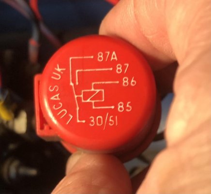
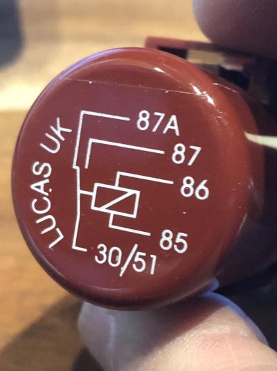
I ordered two relays, and the first one turned out to be bad. Bench testing showed no activation of pin 87 when voltage applied across pins 85 and 86.

The second relay worked fine, on the bench and in the boat. Once installed, the relay did activate pin 87 and the stop solenoid did receive 12V after pressing the stop button at the console (so switch, relay, and wiring OK). However, there was still no "click" from the stop solenoid.

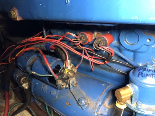
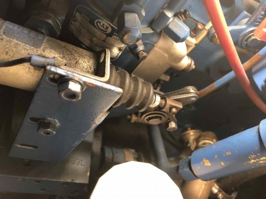
On my Perkins, the stop solenoid pulls on a linkage which lifts a rod in the injector pump and shuts off the fuel supply (see photo). On the opposite engine, I could move this linkage easily with my hand, but not on the Port engine. It was impossible for me to lift the linkage with hand pressure, which turned out to be a separate problem from the relay.

attachment.php


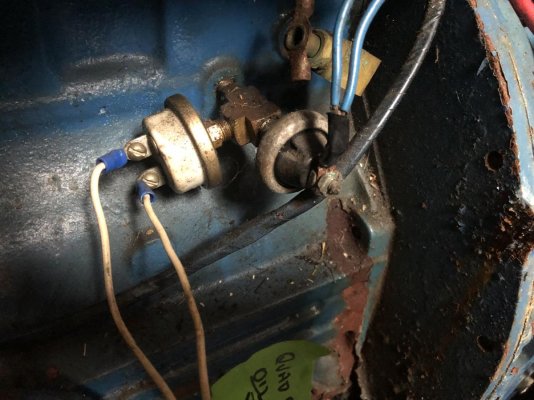
So, I dismounted the stop solenoid from its bracket and examined it. The solenoid core (rod) could be easily moved in/out without friction. Then I bench tested the stop solenoid with a jumper using 12V and it clicked closed just as it supposed to, so definitely not seized up.

Next, I lubricated all the joints on the linkage to the fuel injector, and worked them back and forth with my hand. Once everything was limber, I reinstalled the stop solenoid, and everything worked fine.

In retrospect, probably two problems. Bad relay, and stiffened linkage between the stop solenoid and the fuel injector.

With everything back in place, I can wiggle the linkage with my hand, just as on the other engine.

A few tense moments and scratching my head, but seems to be solved. Lots of help from friends, and TF posts, so many thanks to all.
 

Attachments

  • StopSolenoid.jpg
    StopSolenoid.jpg
    107.7 KB · Views: 77
One of my Perkins stop solenoids was a bit stiff. Sometimes it wouldn't reset after being powered on. Made for a few tense moments trying to start the engine before I remembered, and went to jiggle it. I lubricated it last year and so far it's been behaving.

I had an injector pump rebuilt once, and something inside wasn't perfectly aligned. The stop solenoid pulled the lever OK, but the engine kept happily idling along. I managed to chase down the guy who rebuilt it and he fixed it right there on the dock.
 
Last edited:
Good deal. Now its all fixed, and you have educated yourself (and us) that much further on your boat. I love to see people figuring things out like this and having success. Thanks for the updates.
 
Back
Top Bottom