The stringers by way of the motor mounts on my 1979 Grand Banks 42 apparently are hollow hat sections with maybe 3/4" wood at the top capped by an aluminum extrusion. One of the motor mount bolts came loose. On inspection, it appears to have been threaded only to the aluminum (?) and wood. No metal fastener below as far as I can tell. This seems lightweight for a heavy 120-hp Ford Lehman diesel engine. Does anyone have experience re-securing loose bolts?
You are using an out of date browser. It may not display this or other websites correctly.
You should upgrade or use an alternative browser.
You should upgrade or use an alternative browser.
Grand Banks motor mounts
- Thread starter DSPURR
- Start date
The friendliest place on the web for anyone who enjoys boating.
If you have answers, please help by responding to the unanswered posts.
If you have answers, please help by responding to the unanswered posts.
Barking Sands
Guru
- Joined
- Dec 24, 2019
- Messages
- 886
- Location
- United States
- Vessel Name
- M/V Intrigue
- Vessel Make
- 1985 Tung Hwa Senator
Any way you can take a picture of the set up?
Comodave
Moderator Emeritus
- Joined
- Jul 2, 2015
- Messages
- 21,273
- Location
- Au Gres, MI
- Vessel Name
- Black Dog
- Vessel Make
- Formula 41PC
Welcome aboard. Yes photos would help.
Choices
Guru
- Joined
- Apr 16, 2018
- Messages
- 898
- Location
- Montgomery, Tx
- Vessel Name
- Choices
- Vessel Make
- 36 Grand Banks Europa
Not to hijack thread, but I would like to replace my mounts with exact dimensions if possible.
Any input appreciated.
Any input appreciated.
- Joined
- Nov 8, 2012
- Messages
- 2,315
- Location
- USA
- Vessel Name
- Sandpiper
- Vessel Make
- Bluewater 40 Pilothouse Trawler
Cut or drill an access hole in the side of the stringer and insert a backing plate and nut to bolt the engine mount to.
I weld the nut to the backing plate so it will not spin and ease installation. I cut a slot big enough to slide the backing plate in and install the bolt. Pliers can be used to hold the plate while inserting the bolt. Once the bolt is threaded, the plate will prevent bolt spinning.
Or glue a paint stir stick to the backing plate and hold that while inserting the bolt and cut or break the stick off when done. This method prevents dropping the plate inside the stringer.
Patch the access hole with FG and epoxy.
- Joined
- Nov 8, 2012
- Messages
- 2,315
- Location
- USA
- Vessel Name
- Sandpiper
- Vessel Make
- Bluewater 40 Pilothouse Trawler
Not to hijack thread, but I would like to replace my mounts with exact dimensions if possible.
Any input appreciated.
PYI carriers a wide selection of engine mounts:
https://www.pyiinc.com/engine-mounts.html
The website has instructions on calculating the load weight on each mount in order to choose the correct mount. Or you can contact them and they will assist with the calculation.
Cut or drill an access hole in the side of the stringer and insert a backing plate and nut to bolt the engine mount to.
I weld the nut to the backing plate so it will not spin and ease installation. I cut a slot big enough to slide the backing plate in and install the bolt. Pliers can be used to hold the plate while inserting the bolt. Once the bolt is threaded, the plate will prevent bolt spinning.
Or glue a paint stir stick to the backing plate and hold that while inserting the bolt and cut or break the stick off when done. This method prevents dropping the plate inside the stringer.
Patch the access hole with FG and epoxy.
Thanks. I've come to the same conclusion that drilling an access hole in the side is the best route. The stir stick is a good tip. I still wonder how the bolt was originally secured.
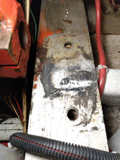
Here is a photo. Below the aluminum cap is 1/4" of filler and below that maybe 3/4" wood. The rest of the stringer is filled with foam. Another thought is to drill a hole from the top (rather than the side) between the two bolt holes and slip a plate with welded nuts inside. I have a photo but don't know how to assign it a URL for posting.
- Joined
- Nov 8, 2012
- Messages
- 2,315
- Location
- USA
- Vessel Name
- Sandpiper
- Vessel Make
- Bluewater 40 Pilothouse Trawler
Here is a photo. Below the aluminum cap is 1/4" of filler and below that maybe 3/4" wood. The rest of the stringer is filled with foam. Another thought is to drill a hole from the top (rather than the side) between the two bolt holes and slip a plate with welded nuts inside. I have a photo but don't know how to assign it a URL for posting.
To post pictures, click on Go Advanced at the bottom of Quick Reply.
On the Advanced Reply to Thread at the top header, click on the symbol that looks like a paperclip. Next to the smiley face.
That will take you to the Manage Attachment page. Click on Choose File and attach your picture. When done click Upload.
Return to the Trawler Forum tab and post.
GB42-424
Member
Engine mount isolators
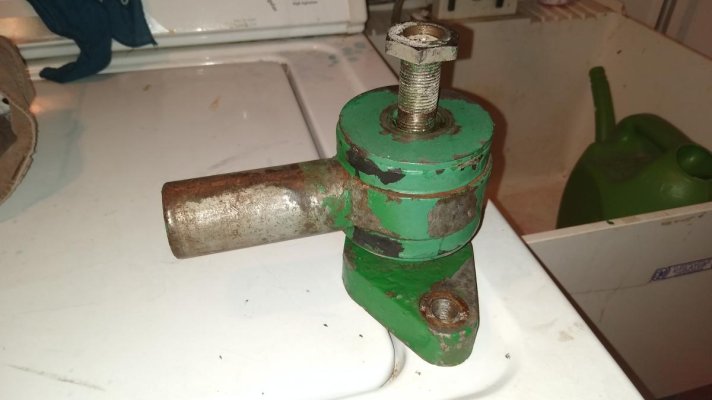
BTW, does your mount look like this picture? I just spent hours this month trying to find a substitute for the rubber isolators. After drilling out the crimped sleeve, I replaced the bottom mount with a polyurethane ATRO part PL1017. AT first I tried a rubber part but the shore hardness (50) was too soft. You need to shave down the diameter slightly. The top mount is the same, but you need to cut off the bottom.
BTW, does your mount look like this picture? I just spent hours this month trying to find a substitute for the rubber isolators. After drilling out the crimped sleeve, I replaced the bottom mount with a polyurethane ATRO part PL1017. AT first I tried a rubber part but the shore hardness (50) was too soft. You need to shave down the diameter slightly. The top mount is the same, but you need to cut off the bottom.
Attachments
BTW, does your mount look like this picture? I just spent hours this month trying to find a substitute for the rubber isolators. After drilling out the crimped sleeve, I replaced the bottom mount with a polyurethane ATRO part PL1017. AT first I tried a rubber part but the shore hardness (50) was too soft. You need to shave down the diameter slightly. The top mount is the same, but you need to cut off the bottom.
Similar, but not exact. There are rubber isolators. Replacement sounds like a difficult job.
Tranquillus
Newbie
- Joined
- Sep 1, 2022
- Messages
- 3
I have the same problem on my starboard engine. After months of thinking about it, last night I decided to try the approach of cutting a hole in the side of the stringer, as suggested above. This morning, I decided to check this form and was delighted to see the same solution suggested!
I have the same problem on my starboard engine. After months of thinking about it, last night I decided to try the approach of cutting a hole in the side of the stringer, as suggested above. This morning, I decided to check this form and was delighted to see the same solution suggested!
If the base metal is fairly thick you could do a thread insert instead.
Choices
Guru
- Joined
- Apr 16, 2018
- Messages
- 898
- Location
- Montgomery, Tx
- Vessel Name
- Choices
- Vessel Make
- 36 Grand Banks Europa
I saw a GB drawing that shows a metal plate 1/2" or thicker inbedded in the fiberglass stringer. The aluminum is just a cap.
This is easy to confirm when you back the bolts out near the seawater pump and find rust.
It is strong enough I suspect the engines could survive a roll over.
I replaced everything but the bolts with stainless when replacing the mounts.
Now you can not feel the engines running.
This is easy to confirm when you back the bolts out near the seawater pump and find rust.
It is strong enough I suspect the engines could survive a roll over.
I replaced everything but the bolts with stainless when replacing the mounts.
Now you can not feel the engines running.
Tranquillus
Newbie
- Joined
- Sep 1, 2022
- Messages
- 3
Thanks for the further feedback. Will keep investigating.
Tranquillus
Newbie
- Joined
- Sep 1, 2022
- Messages
- 3
Curious as to what you mean by replacing everything.
“I replaced everything but the bolts with stainless when replacing the mounts.
Now you can not feel the engines running.“
“I replaced everything but the bolts with stainless when replacing the mounts.
Now you can not feel the engines running.“
Choices
Guru
- Joined
- Apr 16, 2018
- Messages
- 898
- Location
- Montgomery, Tx
- Vessel Name
- Choices
- Vessel Make
- 36 Grand Banks Europa
Go to my blog, grandbankschoices.
The bolts are special, but the motor mounts are not. I replaced everything I could with stainless
Once installed and engine aligned the noise reduction was dramatic. You can not feel the engine when it is running or idling.
The bolts are special, but the motor mounts are not. I replaced everything I could with stainless
Once installed and engine aligned the noise reduction was dramatic. You can not feel the engine when it is running or idling.
Nick F
Guru
- Joined
- Sep 2, 2020
- Messages
- 598
- Location
- Canada
- Vessel Name
- Callisto
- Vessel Make
- 1974 Grand Banks 42 Classic, Hull 433
BTW, does your mount look like this picture? I just spent hours this month trying to find a substitute for the rubber isolators. After drilling out the crimped sleeve, I replaced the bottom mount with a polyurethane ATRO part PL1017. AT first I tried a rubber part but the shore hardness (50) was too soft. You need to shave down the diameter slightly. The top mount is the same, but you need to cut off the bottom.
My mounts looks like the same as this and I would like to renew the rubber pads. Is the ATRO part you listed just a rubber pad, or an entire mount assembly? More details would be much appreciated!
Choices
Guru
- Joined
- Apr 16, 2018
- Messages
- 898
- Location
- Montgomery, Tx
- Vessel Name
- Choices
- Vessel Make
- 36 Grand Banks Europa
Did you try Brian at American Diesel? That's where I got mine.
Similar threads
- Replies
- 15
- Views
- 2K
- Replies
- 3
- Views
- 938
- Replies
- 22
- Views
- 3K
- Locked
- Replies
- 3
- Views
- 3K