Fuel sending unit wiring...

The friendliest place on the web for anyone who enjoys boating.
If you have answers, please help by responding to the unanswered posts.

toocoys

Guru
Joined
Oct 27, 2016
Messages
934
Location
United States
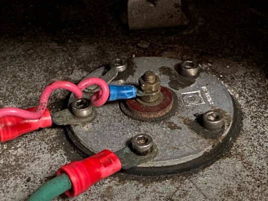
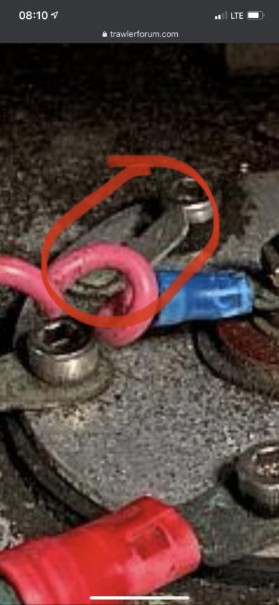
Does this look normal?

They removed all of our two year old gas through the fuel sending unit hole, and had to disconnect it. Upon reinstallation, we put 50g gas in a 300g tank and it’s read empty ever since.

So either the sending unit was connected improperly, or our sending unit doesn’t go all the way to the bottom of the tank. Which is nice to know that there is a reserve.

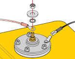
I’ve searched for wiring diagrams for VDO sending units but there are quite a few different ones.
 

Attachments

  • 16D2A8C8-4FF6-4A57-85E2-9E154DB916CB.jpeg
    16D2A8C8-4FF6-4A57-85E2-9E154DB916CB.jpeg
    176.4 KB · Views: 14
o either the sending unit was connected improperly, or our sending unit doesn’t go all the way to the bottom of the tank. Which is nice to know that there is a reserve.

Or the mechanism was hit and no longer will work.
If this were my boat I would be removing the sending unit to inspect and test it.
And replace if need be.
 
I've been trying to bring myself to take it off but I'm paranoid since its gas. I'll have to research how to do it safely.
 
If there is a tab on one of the screws, move the one wire that is not the center one but the other wire on an outer screw over to the one with the tab or put a spade connector on the tab itself.

The green wire should be OK where it is....but not sure.... many Al tanks have a little "L" bracket welded to them for the bonding wire so there is no confusion at the senders.
 
Last edited:
I've been trying to bring myself to take it off but I'm paranoid since its gas. I'll have to research how to do it safely.

Turn ignition off. Or if super safe turn batt switches off/or check for dead center terminal.

Screwdriver.

Plenty of ventillation.
 
You can check with a meter to make sure it is getting power from the gauge.

You can also disconnect from the wires, measure the resistance, and compare it to the table.

Beyond that, you'll need to take it out, cover the opening to control fumes, e.g. with an improvised gasket and cap, e.g. a piece of foam and a heavy book or duct tape or whatever, ventilate well while it is like that and when done, and inspexr or replace the unit as needed.

Once put, you can clean it and test it with an ohm meter and also connected to the gauge.

If needed, you can put it back to close up the hole while ordering and waiting for the replacement.

That bonding wire is odd, especially because there is a gasket between the sender and the tank, but I doubt it is hurting the reading.
 
Last edited:
There is this one little bracket, not sure what it’s for though.
 

Attachments

  • D3AE1A52-92DF-4D65-965E-8ACCB690A3BE.jpg
    D3AE1A52-92DF-4D65-965E-8ACCB690A3BE.jpg
    64.2 KB · Views: 6
Usually neg DC.
 

Attachments

  • download.png
    download.png
    4.6 KB · Views: 23
Sniff with your nose first!!!
With power to the gauge, short the center pin of the sender to the outer aluminum ring with a jumper or screwdriver. The gauge should either peg high or low. Then disconnect the center wire from the stud. The gauge should peg the opposite direction.
For the sender: disconnect the center wire and measure ohms with a DVM. The value should fall between 30 and 300.
It’s possible that the sender float is stuck in place after reassembly.
 
Last edited:
Back
Top Bottom