Fuel Manifold Diagram/Design

The friendliest place on the web for anyone who enjoys boating.
If you have answers, please help by responding to the unanswered posts.

Arthurc

Guru
Joined
Sep 24, 2016
Messages
752
Location
USA
Vessel Name
Sea Bear
Vessel Make
Kadey-Krogen 54
Hi,
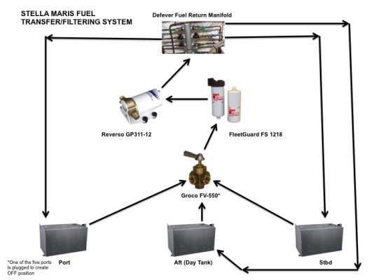
I am designing a revamped fuel system and wanted to get some input from this group. Attached is currently what I am thinking. Arrows indicate direction of flow, I haven't gone so far as to show where each valve goes but that's a next step. Each tank would have its own polishing system on a timer running periodically, since they will be automatic I am wondering if pressure gauges makes sense on them as well so I can remotely monitor if a filter needs changing?

Also note both the Genset and Main have fuel filter systems, I just need to get on the boat to document what they are.

New to this so any feedback of advice would be appreciated.
Arthur
 

Attachments

  • Sea Bear Fuel System.pdf
    27.3 KB · Views: 170
There are lots of ways to do this, but here are some thoughts:


- Do you want to run a rigorous day tank protocol? By that I mean all consumers draw from and return to the day tank only, and fuel only gets into the day tank via filtered transfer. Then the other tanks are just quarantined storage for purchased fuel. On our last and next boats all draw and return is from/to the day tank. I think this is the ultimate in protection against bad fuel.


- I think the way you are set up fuel consumption and fuel transfer have to be from the same tank. This was the case on my last boat and it took a lot of flexibility out of transferring while underway or otherwise running a fuel consumer like heat or generator. On our next boat there is a transfer from and transfer to manifold so you can move (and polish at the same time) from/to any tank independent of fuel consumers which can keep on running.


- It's really important that the returns not be inadvertently closed off. Always returning to the day tank simplifies this. Mine are always open with the handles removed, and one handle in a holder as a "tool" to operate a valve with no handle. Some engines, and I'm not sure if your 6068 is one of them or not, will blow out the fuel injection system if the return is blocked. This has caused very, very expensive damage on some boats when a valve was incorrectly positioned. Some boats remove the return valves completely, but I have found that to create another possible problem. If the return can be submerged at any fuel level, then you can get back siphoning through the return line when changing fuel filters. Consider this carefully before removing the return valves.


- On boat's I've had there is a single transfer/polish pump and filter. This might be a simplification that would work on your boat.


- In a perfect world, draw for polishing should come from the very bottom of the tank, ideally from a sump of some sort. That's where the water and crap will settle.
 
Last edited:
Thanks! As always, great questions.

1. No I don't run a day tank protocol, but would like to be able to, right now my home fueling port (Anacortes WA) is next to a giant refinery, and my understanding is they get their fuel from that source which also explains the best price in the state. I am not worried about fuel quality at home but have future offshore plans a few years from now once her retrofit is complete and I can retire.

2. Really good call out, does this more detailed design address that? I used the second set of input/output on the day tank to separate the fuel polishing and transfer from the main draw, but put valves to run from any tank in the boat in case of emergency.

3. Good call on the siphon effect. Noted the concern of no return by putting locked, via zip tie or removing the handle.

4. Noted and added a Gulf Filter followed by my current Racor's to the xfer pump, this could be used to polish any tank (if I got my design right).

5. Maybe a project for another day :)
I did have her tanks fully emptied, inspected and cleaned out when I bought her, they said they were in great condition and almost completely clean.


I am thinking of making these manifolds myself, thoughts on me welding 304 or 316 stainless tees together to create the exact one I want, I've got a decent set of welding experience and can pressure test as needed.


Thanks again for your thoughts!
Arthur
 

Attachments

  • Sea Bear Fuel System5.pdf
    42.7 KB · Views: 81
Ahh, one more, was thinking about using a Maretron vacuum transducer on the supply side and a pressure on the return side, pointless or interesting?
 
During my refit almost 8 years ago I replaced all 4 tanks. One was weeping and I felt it prudent to replace them all. Original capacity was 3,785 litres, now it is 4700 litres by virtue of enlarged aft tanks.

For the new wing tanks I created day tanks of 385 litres on both port and starboard side. That was about 1/3 of the original tanks. The engine supply and return manifolds can draw from any tank and return to any tank, but in practice the valves are set for using the day tanks only. To fill the day tanks I use a Reverso fuel polisher, as the day tanks have no deck fill. At the time the yard indicated that it would be cheaper to buy the Reverso than to create something from components. If you already have some of the parts required then that may not be the case, but it is worth checking out.

In the top pic you may notice a 'prime' label bottom left of the black polish return label. That allows the Reverso to send fuel through the dual Racors, which can be useful when changing filters. Each engine has dual Racors in addition to the two filters on the 6068's themselves. I draw from one, but in the event of a blocked filter can simply move the lever to the other filter.
28 Fuel polish 2 sml.jpg

The middle pic shows the engine supply manifold and the dual Racors for the port engine. There is a return manifold to the left of that with the dual Racors for the Starboard engine. Oddly, in these pics the engine supply is set to Stbd Aft tank, but so is the return. Normally they are set for the day tanks.

Fuel polish 3 sml.jpg
Fuel supply 4.jpg
 
Last edited:
During my refit almost 8 years ago I replaced all 4 tanks. One was weeping and I felt it prudent to replace them all. Original capacity was 3,785 litres, now it is 4700 litres by virtue of enlarged aft tanks.

For the new wing tanks I created day tanks of 385 litres on both port and starboard side. That was about 1/3 of the original tanks. The engine supply and return manifolds can draw from any tank and return to any tank, but in practice the valves are set for using the day tanks only. To fill the day tanks I use a Reverso fuel polisher, as the day tanks have no deck fill. At the time the yard indicated that it would be cheaper to buy the Reverso than to create something from components. If you already have some of the parts required then that may not be the case, but it is worth checking out.

In the top pic you may notice a 'prime' label bottom left of the black polish return label. That allows the Reverso to send fuel through the dual Racors, which can be useful when changing filters. Each engine has dual Racors in addition to the two filters on the 6068's themselves. I draw from one, but in the event of a blocked filter can simply move the lever to the other filter.
View attachment 98320

The middle pic shows the engine supply manifold and the dual Racors for the port engine. There is a return manifold to the left of that with the dual Racors for the Starboard engine. Oddly, in these pics the engine supply is set to Stbd Aft tank, but so is the return. Normally they are set for the day tanks.

View attachment 98321
View attachment 98322


Very nicely done!!
 
Ahh, one more, was thinking about using a Maretron vacuum transducer on the supply side and a pressure on the return side, pointless or interesting?


I like the newer drawing, especially the "split" manifolds.


And I was going to ask about the transducers. What are you wanting to monitor?


If tank level, I would probably tee them into the bottom sight glass ports, with one transducer per tank. They work really well for fluid level measurement.


If filter obstruction, then they need to be on the output of the filters. I assume you have external Racors or the like not shown for the main and gen and possibly the heater too? And you would need one per filter that you want to measure.


Also, the transducers are different for measuring tank level vs fuel restriction.


Oh, and I see you have a Racor 75900 (dual 900s) for the transfer filter. Do you have duals for convenience of switching and changing filters, or is it for flow capacity? I ask because the Racor 900 is only rated for max 90 gph, so to support the 180 gph pump you would need to run both in parallel. That's fine, but you could also use a single Racor 1000 which is rated for 180 gph, and is probably a lot less expensive than a 75900. And if you want duals for convenience, I think they need to be 1000s, so a 751000 to meet the 180 gph flow rate.


And almost completely off topic, what software do you use for the drawings? I find AutoCAD tedious and overly complicated for drawings like this, so instead use Visio. But my version of Visio is ancient and getting a bit long in the tooth, so I'm somewhat on the lookout for a replacement.
 
Thanks! As always, great questions.

1. No I don't run a day tank protocol, but would like to be able to, right now my home fueling port (Anacortes WA) is next to a giant refinery, and my understanding is they get their fuel from that source which also explains the best price in the state. I am not worried about fuel quality at home but have future offshore plans a few years from now once her retrofit is complete and I can retire.

2. Really good call out, does this more detailed design address that? I used the second set of input/output on the day tank to separate the fuel polishing and transfer from the main draw, but put valves to run from any tank in the boat in case of emergency.

3. Good call on the siphon effect. Noted the concern of no return by putting locked, via zip tie or removing the handle.

4. Noted and added a Gulf Filter followed by my current Racor's to the xfer pump, this could be used to polish any tank (if I got my design right).

5. Maybe a project for another day :)
I did have her tanks fully emptied, inspected and cleaned out when I bought her, they said they were in great condition and almost completely clean.


I am thinking of making these manifolds myself, thoughts on me welding 304 or 316 stainless tees together to create the exact one I want, I've got a decent set of welding experience and can pressure test as needed.


Thanks again for your thoughts!
Arthur

This is similar to the scheme I have. Fuel can be transferred to and from any tank and we run only on the day tank.

I can’t use the supply manifold on my setup because it draws from down tubes. For purposes of polishing, I wanted to draw from the lowest possible point on each tank and fortunately our tanks are plumbed that way.
 

Attachments

  • E6202339-1F3C-461E-AB16-6CC9523980A7.jpeg
    E6202339-1F3C-461E-AB16-6CC9523980A7.jpeg
    60.8 KB · Views: 80
And I was going to ask about the transducers. What are you wanting to monitor?


If tank level, I would probably tee them into the bottom sight glass ports, with one transducer per tank. They work really well for fluid level measurement.


If filter obstruction, then they need to be on the output of the filters. I assume you have external Racors or the like not shown for the main and gen and possibly the heater too? And you would need one per filter that you want to measure.


Also, the transducers are different for measuring tank level vs fuel restriction.


Oh, and I see you have a Racor 75900 (dual 900s) for the transfer filter. Do you have duals for convenience of switching and changing filters, or is it for flow capacity? I ask because the Racor 900 is only rated for max 90 gph, so to support the 180 gph pump you would need to run both in parallel. That's fine, but you could also use a single Racor 1000 which is rated for 180 gph, and is probably a lot less expensive than a 75900. And if you want duals for convenience, I think they need to be 1000s, so a 751000 to meet the 180 gph flow rate.


And almost completely off topic, what software do you use for the drawings? I find AutoCAD tedious and overly complicated for drawings like this, so instead use Visio. But my version of Visio is ancient and getting a bit long in the tooth, so I'm somewhat on the lookout for a replacement.

1. For the transducers are you thinking I could monitor level with pressure transducers? I hadn't thought about that and really good call out, I have the old float style gauges with Maretron senders but they are unreliable at best. I was thinking about monitoring pressure/vacuum in the fuel system but that may not make sense?

2. For the Racor's I just have the 75900's on the boat, would you suggest keeping them and running both to get the 180gpm or get the 1000 and maybe add the 75900 somewhere else or remove it?

3. I use omnigraffle mostly (on Mac) for this sort of stuff, in this case I was lazy and just used powerpoint. I actually find for simple diagrams it works really well, if getting complex or needing specific circuit/mech shapes I use omnigraffle.
 
1. For the transducers are you thinking I could monitor level with pressure transducers? I hadn't thought about that and really good call out, I have the old float style gauges with Maretron senders but they are unreliable at best. I was thinking about monitoring pressure/vacuum in the fuel system but that may not make sense?


Yes, they work extremely well as fluid level sensors. You use a transducer/sensor for each tank, located at or below the bottom of the tank. Then each sensor connects to a Maretron FPM100 which can accept up to 6 sensors. The fluid level can then be calibrated for any shape tank, and is way more accurate than float gauges.


2. For the Racor's I just have the 75900's on the boat, would you suggest keeping them and running both to get the 180gpm or get the 1000 and maybe add the 75900 somewhere else or remove it?


I would use the 75900 for your main engine, and get a 1000 for the transfer filter. The whole point of the 75xxx is the ability to "instantly" change filters just by moving the selector lever, and that matters most with your main, especially if its stuttering in a bad sea way. Then you can change the spent filter cartridge at a relaxed pace.


When transferring or polishing, it's not an emergency if the filter plugs up. You can pause the transfer, change the cartridge, and resume. So no real need for a tandem filter.


3. I use omnigraffle mostly (on Mac) for this sort of stuff, in this case I was lazy and just used powerpoint. I actually find for simple diagrams it works really well, if getting complex or needing specific circuit/mech shapes I use omnigraffle.


Thanks, I'll check it out.
 
Good to know on the transducers, are there specific ones you would recommend (I think they have a bunch of psi ratings? I have a FPM100 in the ER for my water maker and FW system monitoring so easy add, im assuming just adding a transducer on a T at the draw fitting (the fitting on the bottom of the tank) on each tank will work?

I will look at what my main engine fuel filters are as I didn't write them down, they may be a 1000 and in that case I could swap them if the flow requirements are right.
 
Updated diagram showing changes/suggestions. Also Added an intake for a bladder tank which I may add at some point if doing a crossing.

For the Maretron Transducer couldn't I run a hose to it as long as its below the bottom of the tank? Thinking about my ability to change it out since the two fuel connections on the bottom of the day tank are very hard to access.
AC
 

Attachments

  • Sea Bear Fuel System v10.pdf
    44.5 KB · Views: 62
We've been researching fuel manifold design for our vessel refit and this is really helpful information but I'm curious if anyone can point me in the direction of someone who designs these? I love the fancy name plates and also notice that the housing is not just a bunch of NPT fittings screwed together. It looks really clean and thats what we'd like to see on our vessel. Any recommendations for the fabrication and name play design in the US would be greatly appreciated!
 
If you want a custom manifold designed to exactly suit your setup and fit the available space it's not difficult to achieve. A bit time consuming but not out of the question.

I designed and had built for a buddy's boat the manifolds shown below. They were fabricated out of steel square tube and couplings. The valves are compact 1/4 turn. I found a welder who for a modest $$$ amount put end caps on the square tube and welded the couplings in. Added tabs for mounting. Tested the entire setup to 4 PSI overnight. I cleaned the mill scale off of the steel, primed and painted with automotive spray paint then when dry baked it in an oven at just over 100 degrees for 12 hrs to really harden the paint. The valves where then installed to the couplings the threads sealed with good old fashioned rector seal. There are a number of places online to order the lables from. Sorry I don't recall who we used.

The manifolds have been in service for several years now cruising Wa to Ak and back. A big improvement over the collection of valves scattered around the engine room.

fuel%20manifolds.jpg
 
Thank you for that information and those photos. For clarification can you outline your general layout? I see one engine, generator and “filter” (is that for Fuel polishing?) Also two tanks?

Is your return manifold individual channels or does it all sum together in the manifold? I’m not sure how the returns all work themselves out to end up in the respective tanks. I appreciate any info!

Kyle
The boat has two tanks port and starbaoard, typical of most trawlers. One main engine, one generator and the filter + punp. There is also a hydronic heater but it tees off of the generator line so is not included in the manifolds.

Supply connections are at the bottom of the tanks, returns at the top. The original setup was cross connects top and bottom. It all worked well enough with both cross connects wide open all the time and engine and gen drawing from both and returning to both. Again, typical of most trawlers. But I'm not a fan of that. If the boat were to become unbalanced the cross connects would allow the fuel to flow to the low side and make the situation worse.

The problem we wanted to solve was at some point a PO had added more functionality by making it possible to select a tank for supply, a tank for return. He had added a filter and a pump for polishing and transfer. All good goals. But the components were scattered around the engine room. Selection of fuel flow was by way of crude 3 way valving made up of 3 valves and tees. No lables. These clusters at each component. It was a nightmare to operate. Crawling around, turning valves, never quite sure you got what you wanted.

So now with the custom manifolds in normal operation main and gen draw from both tanks and return to both tanks. Essentially the manifolds function as cross connects. Even with the engine(s) not running because the system is full, purged of air and will move fuel as with a siphon. However should you suspect fuel is pooling on the low side and you need to stop that the valves are right there on the manifold, easy to see, easy to operate, clearly labeled.

I wish I still had the diagram I made, but that was several computer and hard drive crashes ago and my backup strategey is not as robust as it could be. I think the owner should have a copy on his boat but I won't be aboard in the foresable future.

The goal and we achieved it was to provide the owner with:
- Easy to visualize and operate complete fuel flow control from one eaily accesable location with the fuel sight tubes in view. Manifolds, transfer / polish pump, polish filter all in one place.
- Ability to draw from both tanks, one tank or transfer while running by drawing from one and returning to the other. I don't recommend this unless you are anal about monitoring fuel levels.
- Ability to transfer with transfer pump
- Ability to polish
- Eliminate the insane 3 valve and tee clusters scattered around the engine room


You are correct the lable filter is for a 'polishing' filter. Not true polishing but a Racor with 2 micron element so that as fuel is moved between tanks it is cleaned. With the pickups at the bottom of the tanks it does a good job of that. As with running polishing can be draw and return to the same tank or draw from one and return to the other. Again I don't recommend that unless you constantly monitor fuel levels. But if there is any doubt about fuel cleanliness, for example as she was out of service for almost 2 yrs, polish by drawing from a tank and returing to that same tank. Start it up and let it run for hours while the owner attends to other things. No risk.

I hope this helps.
 
That is very helpful - thanks for the insight and input.
 
The fuel manifold on my NN46 was a nightmare.
Keep it simple, tag everything.
Diagram it on paper for your reference and the next owner's.
There is also an aluminum plaque you can have made, once you diagram it on paper, properly. Glue that up in the engine room, so it doesn't get 'lost'.
 
Back
Top Bottom