Exhaust System Design - Comments?

The friendliest place on the web for anyone who enjoys boating.
If you have answers, please help by responding to the unanswered posts.

mvweebles

Guru
Joined
Mar 21, 2019
Messages
7,215
Location
United States
Vessel Name
Weebles
Vessel Make
1970 Willard 36 Trawler
I am refitting my Willard 36 for an extended cruise from California to Florida. I've had her for 20+ years. Wm Garden designed her low in the water which is great for many things......except it does confound the exhaust system a bit. I've never had any issues, but want to take the opportunity to improve her if possible.

QUESTIONS:
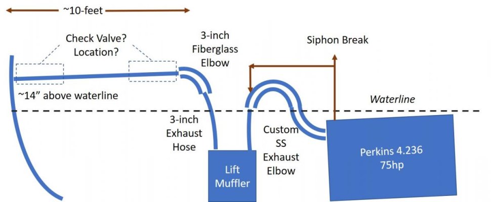
1. Anyone have experience with Centek inline back-flow preventers? I realize its functionally the same as a rubber flap on the flange where the exhaust exits the boat, but maybe something better?
2. Assuming the Centek check-valve has merits, where should it be installed - as close to the engine as possible, or near the hull exit? My thinking is to have it as close to the engine as possible, but maybe not.

See attached diagram.

Engine is out of the boat, so I have some flexibility - general comments are welcomed too.
Thanks in advance - Peter
Exhaust Config.jpg
 
Weebles
I'd recommend you install it where the access for install and servicing is best. It will add some constriction. Are you sure you need it? Has the vessel's exhaust system has done OK for 40+ years without it?
 
I am not a big fan of those check valves. I believe that you should design your exhaust system so it doesn't need one. But if that is not possible, they are better than nothing, but they may be nothing if they stick open and you will never know that unlike the exhaust flap that you can see. I much prefer the exhaust flap such as Centek makes.

So with that out of the way, first look at the attachment (courtesy of Tony Athens) which shows a proper lift muffler installation.

The outlet from the muffler rapidly slopes down near the water line and then continues at a moderate slope until it exits near the water line. I don't really think you need to make that transition, just slope it down evenly until it exits a few inches above the water line. Yours has it exiting much higher. Drop it down so it exits near the water line. In your installation even a moderate stern wave will push water up and fill your lift muffler. It will continue to fill until it forces water up over the loop into the exhaust port and then into the engine.

I assume that you don't have room to make the loop from the engine to the muffler higher as shown in Tony's diagram. Here is a solution I found on my Mainship 34T with similar geometry constraints: They put a drain hose connected to the bottom of the lift muffler (Centek's mufflers have this connection but plugged off) and route it horizontally to exit the boat at the side a few inches above the water line. Use 1/2-3/4" hose. This equalization hose assures that the water in the lift muffler can't get any higher than the thru hull exit and will never get high enough to go over the exhaust loop into your engine.

Good luck with your design.

David
 

Attachments

  • Tony's lift muffler design criterion.gif
    Tony's lift muffler design criterion.gif
    86.2 KB · Views: 83
David
You are correct on hesitations of inline check valves.

I'm not sure if your drawing matches Weebles engine placement below the waterline. His setup may more resemble the thousands of "no problem" sail boat setups, or not.

Weebles, by your drawing you don't have an exhaust elbow shower head. Manicooler design?
 
Weebles
I'd recommend you install it where the access for install and servicing is best. It will add some constriction. Are you sure you need it? Has the vessel's exhaust system has done OK for 40+ years without it?


I've owned her for over 20-years, and she's a 1970 so just turning 50-years old. The original owner built her for fishing in Baja and went from from Newport Beach CA to Cabo (850 nms) several times back in the 1970's. So yea, I have to ask myself 'if it ain't broke.....' It's just part of the overall boat that has never set well with me - would prefer to get a loop much higher off the waterline than just 10-inches (bottom of the 3-inch exhaust hose, which naturally sags a bit). Add a full load of fuel, and well, you can see my concern.


I'll drop Centek a note and see how it's constructed. It looks bulbous enough that perhaps it doesn't add meaningful constriction. I might also consider replacing the hose with rigid fiberglass to get a more fair and straight downward sloped run.


Thanks Sunchaser -
 
.... look at the attachment (courtesy of Tony Athens) which shows a proper lift muffler installation.

The outlet from the muffler rapidly slopes down near the water line and then continues at a moderate slope until it exits near the water line. I don't really think you need to make that transition, just slope it down evenly until it exits a few inches above the water line. Yours has it exiting much higher. Drop it down so it exits near the water line.


Thanks David - this is helpful. I had thought about lowering the outlet. I'm nowhere near the boat, but will take a look next month when I make my visit on the refit in Mexico. I seem to recall I have steering gear in the way. My boat has an old Wagner T-Ram steering setup which is much different than traditional hydraulic ram. It's a great system, but bulky, especially when tucked into a canoe-stern. I may look at moving it off-center a couple feet.


My lift muffler is entirely below waterline by over 1 foot. But I like the idea of an over-flow.


I will tell you that after 20+ years of ownership, trying to get suitable gear into a 36-foot boat is a challenge. Especially a double-ender vs a transom stern with a huge lazarette. Thank goodness I am [mostly] in the simple-is-better camp
 
How many gallons do you think the water lift muffler can volume is? Just a visual estimate is fine.

Is the top of the muffler below the exh manifold outlet on the engine?

Got a pic of the back of the engine showing exhaust mixer/riser?

Based on the sketch, design looks good and I see no need for a check valve. Regardless of design, checks in this service do not tend to be reliable. Harsh environment.

If you do choose to put one in, I don't see any difference between the two proposed locations.
 
Peter,
Maybe contact Tony Athens at Seaboard Marine in Oxnard, Ca. for advise. He usually responds to forum posts on his site (sbmar.com), or you can send him an email. Be aware, that if you do contact him, he will definitely ask for lots of photos of the current engine and exhaust setup and will ask many questions to aid him in determining what will work for your boat set up. Usually he provides "free" advise, but you may even want him to make up a new exhaust elbow for you (if needed)??
Just from a common sense perspective, I agree with not relying on a check valve whose operation is difficult to impossible to monitor, where failure of that valve could have dire consequences.
 
Surprising, of the 1000 pictures I have of the ongoing refit, I do not have a good one of the engine. Facing aft - here is a pic right after the engine was pulled a few months ago (FYI - everything has been rewired, painted, new insulation, and new tanks). I've put some notes in showing approx waterline and where the lift-muffler goes. I'd guess the waterlift is around 2.5-3 gallons capacity. The break where the exhaust goes through the bulkhead needs to be close to the centerline as there are water tanks on the after side of the bulkhead.

Ski - thanks for the comments. I'm leaning to going with nothing. Welcome any improvement comments though.

Many thanks to all

Peter
Engine Room.jpg
 
I had my re-power done at Port Townsend Shipwright's CoOp. For the exhaust they did pretty much all of the above. Namely:
- custom exhaust pipe (insulated) from turbo to an elbow that is just below cabin sole
- water injection below the elbow on the downstream side,
- hose to waterlift muffler,
- hose from waterlift muffler up to touching salon sole
- fiberglas tube to the backflow unit,
- backflow preventer (about 2' from transom)
- slope to just above waterline using fiberglass tube,
- flap at outlet.

The only thing I don't have s the drain/equalising hose. Almost 8 years and no issues at all.
If you still have clear access then I'd be inclined to do it the way mine is. Yes, belt & suspenders approach but if its easy to do because of access, then why not?
 
how much more height is between the beams ? my exhaust runs straight up to the ceiling and has a 180 and comes back down .this stops it from running back into the muffler. a good exhaust flap would a help keep swell from pushing it back over the 180.
 
Custom exhaust elbow comes off engine and goes up with a 180 above waterline. After the water injection, continues to lift muffler via rubber hose.
 
Ideally the first turn or high point rise after the turbo will be higher than the one after the muffler. That way even if the muffler does get backfilled the water should not get past to the engine.

If it is lower than the muffler or the after muffler turn and water does fill the muffler then water could get to the engine.
 
my 180 is after the muffler it does not have a syphon break . from the engine to the lift muffler is gravity fed no rise . sorry it my last post was confusing .
 
Can the exhaust hose coming out of the muffler be longer/ taller? Or does the elbow touch bottom of the floor above?

My waterlift muffler is below the waterline but it's exhaust goes up 4 feet to the elbow which touches the bottom of the floor. Then it slopes down towards the transom, which is a vertical drop of 2 1/2 feet. The horizontal distance from the muffler to the transom is 10 feet.

I don't have flappers or a check valve.
Sounds like your Bluewater has a much higher sole. Mine is no more than 14-inches or so above waterline. Very good fit sea keeping, but for systems, a challenge. Given the very gradual downward slope, wonder if the back flow preventer might make sense. But again, after 50-years, am I solving a problem that doesn't exist?
 
A big beam sea and a rolling actinon of the boat might be enough to fill the exhaust line while anchored.


Simple cure would be a higher loop (similar to used in overboard toilet discharges ) in exhaust tubing


A bit harder is a North Sea Exhaust where the exhaust has 2 outlets port & stbd.
 
On my boat, the exhaust from the engines feeds into a bottom side input on a water lift muffler. Exhaust comes out the top side of the muffler, then drops about 15 - 18 inches straight down. Then a slight down slope from there to the transom exits which are pretty much at the waterline (and wide open). Even if you shove water into the transom exits, it's unlikely that the water will travel 12 feet forward and still have enough energy to climb the vertical section of pipe to get into the muffler.
 
mvweebles, I had to design and build an exhaust system two years ago so I started with a white paper from northern lights called don’t drown me as a road map. Can’t seem to upload it here but it’s easy enough to find on their site. One of the things you need to consider is that 150” of 3” hose holds about 4.6 gallons of seawater. Get that moving while you are pitching and it’s quite a bit of force to deal with. You’ve had the boat long enough by now to realize that it ain’t broke, so trust but verify, and be extra careful when evaluating any big changes. William Garden was no slouch.
 
You’ve had the boat long enough by now to realize that it ain’t broke, so trust but verify, and be extra careful when evaluating any big changes. William Garden was no slouch.


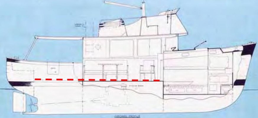
Attached is an original line drawing from a 1960's era brochure of the W36. Note how low the sole (red dashed line) is compared to the waterline - maybe 14-inches, and thus the issue of getting adequate slope.


At this point, I'm looking at lowering the outlet a bit, and will make a decision on the check valve at that point.


Thanks to all - the NL article was also helpful


Peter
W36 Line Drawing.jpg
 
Many sailboats, and your hull looks kind of like a sailboat, run their exhaust up inside the gunnel to get way up above the water line then back down again. Looks like you could get maybe 3' above the water line if you could do that.


David
 
On my generator exhaust, the hose exits the waterlift muffler and goes up vertically through the floor to a loop. The hose from the loop goes back through the floor and slopes to the transom.

Having the top of the loop above the floor allowed for a greater slope to the transom outlet.

The loop is hidden with an enclosure.
 
What about dumping it out the side? My generator dumps a few inches above waterline, 2/3 of the way forward on one side with a downward and aft facing clamshell over the output. Exhaust slopes down from the injection elbow to the muffler, up out of the lift muffler, then a fairly steep slope down to the discharge. It's worked well for years (and even self drains enough that it doesn't have a flooding risk during long cranking). The clamshell makes it fairly hard to push water back into the outlet.
 
Centek makes great products, I've used them for years and routinely send my boat building clients to them for design assistance. Having said that, I'll echo the thoughts of others by expressing concern about exhaust check valves, primarily because there's no way to be sure they are working. I've removed a handful that were literally hollow, the guts had disintegrated. I would not want to rely on it. As an alternative, you might simply go with an external flap, at least that you can monitor.

This article covers a range of exhaust design details, you might find it helpful. https://stevedmarineconsulting.com/wp-content/uploads/2014/03/ExhaustSystems170-FINAL.pdf

While you are refitting the exhaust, I would strongly recommend the addition of a wet exhaust temp alarm, they have saved many operators from damage and expensive repair bills when cooling water is lost.
First, thanks so much for taking the time to assist. Based on input from several others, I had abandoned the check valve idea and am working to understand how to get a better slope into my exhaust hose. Boat is in Ensenada and I'm in Florida right now, so need to wait for my next trip there in a few weeks

Second, your article talks about using a thermistor set at around 165 on the hose, just after the mixing elbow. Any guidance on sourcing this? Is this an off the shelf item?
 
Someone may have suggested a thermister but that also needs a proper unit to read it.

Tony Athens strongly recommended the Airpax snap switches which will simply close setting off the simple alarm. You just have to chose the temp needed for it to close.

http://airpax.sensata.com/pdfs/5003.pdf

YOu can contact Seaboard Marine to buy them or chase them.

www.sbmar.com

If you go to Seaboard tell them what it is for. You should be able to find and read TOny's article about setting up the alarm.

Installed in the proper spot on the exhaust it will warn of a loss of raw water long before the coolant will tell you anything is wrong.
 
First, thanks so much for taking the time to assist. Based on input from several others, I had abandoned the check valve idea and am working to understand how to get a better slope into my exhaust hose. Boat is in Ensenada and I'm in Florida right now, so need to wait for my next trip there in a few weeks

Second, your article talks about using a thermistor set at around 165 on the hose, just after the mixing elbow. Any guidance on sourcing this? Is this an off the shelf item?

Yes, it is an off the shelf system, affordable too. This article will give you a hint... https://stevedmarineconsulting.com/onboard-alarms-part-i/ Pay special attention to the photo captions.
 
The exhaust hose alarm (just as shown in Steve's article) looks like a zap strap that goes around the exhaust hose right after the mixing elbow (water injection point). I know of 2 brands, Borel and Aqualarm (there could be more). I installed the Borel on my boat because it goes into alarm about 10 degrees earlier than the Aqualarm. For either, you will need the panel with audible alarm (it is loud) to mount near the helm. It will alarm with a buzzer and a warning light, and it can be muted. For a type of redundancy, I also installed an Aqualarm flow alarm that goes in the raw water hose between the sea strainer and the raw water pump. This one could save having to replace an impeller if you forget to open the strainer intake. These alarms cost in the ball park of $100 each, plus the panel (about another $100) so they are very well worth the expense.
My exhaust alarm was the only thing that warned me that my exhaust hose was overheating from a failing exhaust elbow. At all other locations (as verified by IR gun) the (engine) temperatures were great! This saved me from possible turbo or even engine damage.
 
I have a similar but different make boat and I ran dry exhaust up to 18 inches above the waterline and looped it down to attach the water injection elbow. from there it's pretty standard with a Centek waterlift leading to a Vetus gooseneck at the stern (no transom, double ender). There's plenty of system volume to contain the backflow when shutting the engine down and plenty of height to ensure zero water gets even near the exhaust manifold. The dry portion is simply black pipe fittings with custom made exhaust blanket covering it, cheap and easily replaced. The pipe fitting at the manifold is a tee with a reducer on the down side and an all metallic drain valve to open when shut down to prevent any condensation or moisture getting into the engine.
 
Attached is an original line drawing from a 1960's era brochure of the W36. Note how low the sole (red dashed line) is compared to the waterline - maybe 14-inches, and thus the issue of getting adequate slope.


At this point, I'm looking at lowering the outlet a bit, and will make a decision on the check valve at that point.


Thanks to all - the NL article was also helpful


Peter


Peter,
I thought I would pass on a modification a previous owner made to Hull No 34.
The sea water is injected at an elbow directly on the manifold, with a hose to a water lift aft of the Velvet Drive. The discharge from the water lift goes vertical to a 3” fabricated fiberglass goose neck pipe that penetrates the cabin sole vertically to a point about 16” above the water line, then back down to a horizontal run immediately below the sole. A hose then slopes gently down to a discharge just above the water line at a point about half way between the boarding door and the aft point of the stern.
The gooseneck blocks part of the door as it has to be located inboard of the water tank. The stbd door half is fixed, held on by screws and angle brackets so it can be removed to take something large in or out.
While we loose half the door, we gained a large cabinet with space for microwave and Kuerig, and extra storage. The cabinet is more useful than the double door.
The goal of course was to get the 16” drop from the high point of the exhaust pipe to the water line.
I will try to post some photos, my attempt to attach them to this post failed miserably!
Bill
 
Last edited:

Latest posts

Back
Top Bottom