Exhaust Manifold Overheating, Detroit D. 4-71N

The friendliest place on the web for anyone who enjoys boating.
If you have answers, please help by responding to the unanswered posts.
The mixing/diverting valve would normally be a 3-way valve, which in your sketch, would replace the bottom tee in figure 1. It would be plumbed to direct flow through the bypass (vertical) leg so the keel cooler gets no flow until the valve's set temperature is reached, at which point it starts to open, allowing some flow through the cooler, and opening progressively more as the temperature of the coolant rises. When fully open, the bypass leg is closed to flow, so it's all passing through the keel cooler. It will remain partially 'open' if the temperature so requires, like if operating in very cold sea water with light engine load. Speaking in general terms, of course.

Google "thermostatic mixing/diverting valve" and pick the first link, which should be thermomegatech.com/product/1-thermostatic-mixing-diverting-valve but with the appropriate stuff at the head and tail. If I post a link, it goes to the mods for approval (I guess because I'm a noob), so this should be faster.

And I'll remind you again that I'm not familiar with marine keel coolers, and my marine diesel experience is in relatively puny sailboat auxiliaries with fresh water cooling with raw water directly to the heat exchanger. So do consult someone who knows how to plumb that DD to a keel cooler and cabin heater properly.

But what I linked to is pretty standard stuff in hydraulic cooling systems as well as other applications where temperature control is important, but fine control is not required. Like engine cooling systems with remote heat exchangers with circulating pumps (like a cooling tower). I just wanted to show you what a typical 3-way thermostatic diverter looks like and how it's plumbed.
 
I'm not at all familiar with DDs, but why isn't this plumbed such that the built-in thermostat on the engine handles all this? Every engine I have ever seen does this as part of its basic function, diverting some amount of coolant flow through an external loop for cooling. That external loop can be a radiator, a sea water heat exchanger, or a keel cooler. But they all work the same way.

Has this engine been modified in some way to defeat this? Earlier on there was some comment about removing the tube bundle from the heat exchanger? What's that about? Is this originally a heat exchanger cooled engine, converted to keel cooling? If so, it doesn't sound like it was done correctly and is likely the source of your problem.
 
ND
You are getting a lot of advice, some conflicting with others. Suggest you do three things.

1. Ignore the heating loop for the time being, concentrate on a flow sheet for getting the keel cooler and engine performing properly. On a PM basis pick a TF pro to assist you. In developing the flow sheet and specs, I recommend Psneeld. TT's comment about the heat exchanger bears scrutiny.
2. There are hundreds of perfectly operating keel cooled vessels in the AK fishing fleet, talk to a few of these guys to get eyeball success stories. Take notes and pictures.
3. Once you get the engine only flow sheet finalized and agreed to (?with the assistance of one trusted TF ally ?) install it and trouble shoot. All of the hoses and parts can be found at your local NAPA store. I personally have used the Ketchikan NAPA store for re-plumbing parts for cooling systems. Report back here if you care to.

As far as the coolant heating the cabin, there are several good ways to do it, none of which will alter your newly set up engine coolant loop. FF's advice on a bus heater (Red Dot) is a good one. There are others. Again, fuss with the heater secondly. Ignore the old tail wagging the dog stuff.
 
Last edited:
Engine thermostat should handle all temperature control needs whether KC, radiator or heat exchanger cooled. There should be two circuits on the engine: One through the block and head, the other though the manifold. Both flows in parallel. Coolant circulates through both with tstat closed. Once tstat in water manifold senses heat, it cracks open slightly and some hot flow goes to KC, and some cool flow comes into water pump from KC. In some situations, the tstat will cycle from open to closed to open, but this usually causes no problems. Probably invisible. No different than driving a truck with light load in subzero temps.

In some engines the bypass flow path used with tstat closed gets blocked once tstat is full open. I don't think the DD 471N is set up that way.

Do not see the need to install any other thermostatic valve beyond what came with the engine. Not needed.

But would like OP to check that a factory tstat is in fact installed. Without a tstat, the driving head in the manifold loop will be reduced, and may be the basis for this problem.

I think the problem is mostly related to reduced flow in manifold which can be explained by restricted fittings and hoses and sending the same flow out to a heater.

These systems are truly engineered. Might look simple, but there were a lot of decisions made regarding flow rates, tstat behavior, heat rates, etc. Modify any part and you may get weirdness.

Ski, It would be a relief to not need to mess with the keel cooler flow. I have attached a diagram that illustrates the coolant flow path as I believe it is.

When trolling (40F water) at 600RPM the engine temp stays 40F less than the 170F thermostat rating. The thermostat housing was opened and I found 2 ea. 170F thermostats. They were tested and appear to be operating as intended. Is it possible that there is enough coolant flowing through the thermostat by-pass route via the exhaust manifold loop that the thermostats never open? If so, what solutions might there be?
 

Attachments

  • IMG_2044[1].jpg
    IMG_2044[1].jpg
    79 KB · Views: 52
More engineering input from a friend...


"Since the engine is now keel cooled and the fresh to raw water heat exchanger has been removed it should be looked at much as a raw water cooled engine with the fresh water pump doing all the circulating between the engine and the keel cooler. These systems typically use a 3-way "Amot" type valve that when cool circulate water around the keel cooler but when hot pass all or part of it to the cooler. The engine mounted thermostat does the fine tuning while the Amot does the heavy lifting and full circulation is always available through the system.

The FW pump should take an unimpeded suction on the keel cooler.

There is a blanking plate shown where the FW heat exchanger was removed. There should be a fitting the same size as the exhaust manifold inlet installed on that plate with a same size hose or tube fitted between. The outlet from the manifold should go to a fitting on the water pump suction side. This assures adequate flow regardless of thermostat condition.

The outlet of the FW pump should discharge to the oil cooler housing as original. Any auxiliary flows such as for a water heater should be valved and connected between pump discharge and keel cooler inlet. "
 
Ski, It would be a relief to not need to mess with the keel cooler flow. I have attached a diagram that illustrates the coolant flow path as I believe it is.

When trolling (40F water) at 600RPM the engine temp stays 40F less than the 170F thermostat rating. The thermostat housing was opened and I found 2 ea. 170F thermostats. They were tested and appear to be operating as intended. Is it possible that there is enough coolant flowing through the thermostat by-pass route via the exhaust manifold loop that the thermostats never open? If so, what solutions might there be?

Again, I have zero experience with DDs, but I would expect the outlet of your Cabin Heater to go back to the water pump, not to the KK. That whole loop of the compressor+manifold+heaters I think should circulate from/to the engine, and not prove a bypass path to the KK as it is now. As it is now, you have an unconstrained flow through the KK even when the thermostat is closed. That would explain your cold running under light load. And when the thermostat is open, most flow will run through that path to the KK with less flow through the compressor+manifold+heaters, and not provide sufficient cooling of the manifold.
 
"The engine mounted thermostat does the fine tuning while the Amot does the heavy lifting and full circulation is always available through the system."

YES!

In operation once the system warms after engine start, the engines KK return temp (160F?) will be fine for box heaters or FW heating .

Not attempting to heat the entire ocean the engine temp will normalize and only vary a bit , for a while, on load or RPM changes.

One note on DD is that operation over 200F is not recommended.

The water circulating in the head can form steam pockets and overheat.

At 200F , ease off ,190F is fine forever.
 
Last edited:
The flow diagram will not work properly as drawn. A couple problems: 1. the outlet from the cabin heater should go to coolant circ pump suction, not into KC. 2. The engine oil cooler is factory mounted between circ pump and engine, so maybe the "oil cooler" is the gear oil cooler?

As drawn engine will sub cool at low load. And depending on flow restrictions in manifold loop, there may not be enough cooling in that loop at high load.

Ski, would a 3 way thermostatically controlled diverter valve plumbed as shown on the attached diagram solve some problems?
 

Attachments

  • IMG_2043[2].jpg
    IMG_2043[2].jpg
    57.4 KB · Views: 41
Ski, would a 3 way thermostatically controlled diverter valve plumbed as shown on the attached diagram solve some problems?


What I can't understand is why you wouldn't just plumb up the engine as it's supposed to be, rather than adding more stuff to work around the errors made in the past.
 
Step 1. Plumb it as the factory had it plumb.
Step 2. Then and only then, begin to modify the system conservatively, one change at a time and see how the cooling system and exhaust manifold behaves. Back out the change before you add a second change before removing and inserting another change always watching for behavioral changes in the cooling system and exhaust manifold temp. (Make a note of the SW injection temp too)
When you have tried each individual change, add in the 2nd change watching the behavior of the cooling system and exhaust manifold temp etc.
Ideally, you can get the system working as you wish, without adding manual valves, just thermostats of various opening temps. Putting in valves mean you must remember to adjust the valves.
Worse case, I think, riding down the backside of a wave and remembering you forgot to adjust the valves. LOL
 
Last edited:
Again, I'm not seeing the problem: dry exhausts or headers run at several hundred degrees. Are the blankets or the lagging missing? What manifold are we talking about that is supposed to be cool but isn't on an engine with a dry exhaust? Does DD water cool the exhaust manifold on dry exhaust installations?
 
Again, I'm not seeing the problem: dry exhausts or headers run at several hundred degrees. Are the blankets or the lagging missing? What manifold are we talking about that is supposed to be cool but isn't on an engine with a dry exhaust? Does DD water cool the exhaust manifold on dry exhaust installations?

Step aboard a Nordhavn to see how a yacht builder does it. Or a commercial tug or fishing boat. The OP has stated the problems as best he can. Now for the solutions, which seem to be properly narrowing down.
 
Again, I'm not seeing the problem: dry exhausts or headers run at several hundred degrees. Are the blankets or the lagging missing? What manifold are we talking about that is supposed to be cool but isn't on an engine with a dry exhaust? Does DD water cool the exhaust manifold on dry exhaust installations?


Coolant jacketed exhaust manifolds are very common in marine engines, regardless of wet or dry exhaust. The wet/dry difference happens at or down stream of the exhaust elbow. My Deere engine, for example, has a coolant jackets exhaust manifold and turbo. Both run at coolant temp.

This DD appears to have a coolant jacketed exhaust manifold, yet it's temp varies widely. But it's just one of several symptoms, all of which lead back to an improperly installed and plumbed cooling system. Plumb it correctly, and I'll bet it will all work just fine, like the thousands of DDs that have served over the years.
 
Take a heat gun..... drive your car for 100 miles at hi way speed and take a reading on the exhaust manifold.
 
Take a heat gun..... drive your car for 100 miles at hi way speed and take a reading on the exhaust manifold.


Ok, but that's fundamentally different from a coolant jacketed exhaust manifold. The jacketed manifold will be at engine temp more or less across all loads.
 
"Does DD water cool the exhaust manifold on dry exhaust installations?"

Usually as the KK has vast capacity , so any heat that needs to be removed is no hassle.

" The jacketed manifold will be at engine temp more or less across all loads."

However the exhaust gas temperature will vary greatly due to loading.

Good exhaust lagging will allow the engine room to remain fairly cool,about same temperature as wet discharge exhaust ER.
 
The flow diagram will not work properly as drawn. A couple problems: 1. the outlet from the cabin heater should go to coolant circ pump suction, not into KC. 2. The engine oil cooler is factory mounted between circ pump and engine, so maybe the "oil cooler" is the gear oil cooler?

As drawn engine will sub cool at low load. And depending on flow restrictions in manifold loop, there may not be enough cooling in that loop at high load.

Ski, I have made the change to the attached flow diagram per your suggestion no. 1 above. The cabin heater outlet is now flowing into the suction side of the FW pump. When you say on the suction side I assume you mean close to the pump on the suction side. Strictly speaking on a loop system the location where suction stops and pushing pressure begins is not easily known.

Comment about no. 2: The oil cooler shown on the diagram is the engine oil cooler which is factory mounted below the water tank and heat exchanger on the front of the engine. My feed from the keel cooler is connected to the engine driven pump located externally of the engine on the back upper portion of engine. So the FW flow to the engine oil cooler is not between the engine and the FW pump where you say it should be. I'm thinking there is no external access to the engine side of the FW pump to plumb the FW flow into the oil cooler before the engine. I will have to take a close look at the engine when I'm back in Alaska where the boat is. Note: There is no need for a transmission oil cooler since the gears are bathed in oil. It's a manual shift twin disk X8070 "crash box". Yes, Old School transmission.

My son, who is in Alaska is working on improving the flow through the loop which has the exhaust manifold to hopefully prevent the exhaust manifold from overheating. Thank You.
 

Attachments

  • IMG_E2049[1].jpg
    IMG_E2049[1].jpg
    79.8 KB · Views: 37
"What I can't understand is why you wouldn't just plumb up the engine as it's supposed to be, rather than adding more stuff to work around the errors made in the past."

Most of these engines were Grey Marine conversions that have wet exhausts and sea water pumps and heat exchangers,from the factory.

Going to dry stack with KK is a quite different installation.

This is a "new to me" boat with no documentation related to the correct way to keel cool this engine. It was purchased after the owner died and no one in the family or otherwise can tell me anything of the previous use and history.

The present keel cooling system is not adaquate. Previous posts have documented the KC performance problems. I need a good design before making any changes.
 
ND-Your proposed plumbing fix looks like it is worth a try.
 
Here are a couple pics out of a 1974 DD shop manual for 71 series. It's a method using the original thermostats.
 

Attachments

  • 671_keel cooler.JPG
    671_keel cooler.JPG
    63.5 KB · Views: 41
  • 671_keel cooler1.JPG
    671_keel cooler1.JPG
    52.2 KB · Views: 49
ND-Your proposed plumbing fix looks like it is worth a try.

Ski, I will proceed to make 2 changes. 1. Reduce flow restrictions in the cooling loop which includes the jacketed exhaust manifold. 2. Return the outlet of the the exhaust manifold loop to a location near the FW pump on the suction side. The work will not be able to be completed for a few weeks when I return to Alaska. I will post the results.

Thank you for your suggestions.
 
Folks, I apologize for the length of this and wouldn't blame you for passing over it. For the others, get a cup of coffee and get comfortable.
It addresses the keel cooler and then, the analog verses the digital read outs.
------------- Section One --- Keel cooler
As I understand this thread, a PO of this trawler changed his engine to a dry stack and keel cooler???
If that be correct, I have a few question. When the boat was hauled was there a pocket in the hull for the protection of the keel cooler or was the keel cooler just stuck against the hull without protection from snags and trash?
A picture of the outside installation would be nice. The dimensions would be nice, plus the GPH of the cooling water pump. Is this an actual keel cooler or a home made keel cooler? It was designed for what average ocean temp? Designed for what average speed.
Who did the math to determine the necessary size of the keel cooler?
I can no longer do the math..... too many dead brain cells.
I am just trying to get more information for a 'whiz kid' willing to do the math.

My experience with keel coolers is limited but, I will give you a quick recap. I had a 46ft Nordhavn, dry stack and keel cooler factory designed and installed, tucked neatly factory designed pocket for the safety and protection of the keel cooler.
Bringing the boat down from LI to Miami, WOT, the temp would slowly rise and exceed the max recommended temp.
Cure; reduce the RPMs until the temp was back in the normal operating range then back to WOT. We carried out this routine as necessary, maybe once or twice every couple of hours. (John Deere engine, factory installed)
When the boat was hauled, the keel cooler was neatly tucked away in a pocket. I had the engine boiled out then, I had the keel cooler removed and sent to a radiator shop for further cleaning, visual inspection and to be boiled out again.
After reinstallation, and testing, the temp would still rise beyond the recommended temp but not as quickly so I guess it was a positive effort.

My only conclusion can be, the keel cooler was designed for an average speed or something less than WOT, for hours, and at unspecified average ocean temp. The designed specific temps and speed I do not know.
Results, I just learned to live with it and put the temp check on my routine instrumentation check. The temp would take hours to exceed the recommended 'high' temp.

------ Section two... analog vs digital read out. -----

All my instrumentation was analog so I would put small pieces of red tape at the maximum recommended temps and minimum pressures.
One BIG advantage of analog instrumentation is the 'visual quick check.' Normal pressures and temp are designed to indicate in the middle 1/3 of the gauges and read outs. I have seen some folks modify the instrumentation mounting, as necessary, to put the 1/3 at the top so when doing a 'quick sweeping visual check', anything outside of the center 1/3 would quickly catch the eye of the operator.

Example: many years ago, the family had race boats. Naturally, way back then, the only option was analog instrumentation. Each of the read out were twisted and turned and mounted so the expected normal range was at the top.

Another example: When I was on nuclear subs, there were many many many analog temp and pressure read outs. These had to be logged at least once an hour, to show tends. Again, each instrument was mounted so the expected normal operating range (center 1/3) were at the top.
I guess that is why I favor analog read out. A quick glance (center 1/3) gives a good indication of what's happening. With digital read outs, for me, takes longer to observe and digest the information. Gotta look, remember the normal operating temps and pressures, digest the information and make a decision.
Sort of like the digital watches. In reality, no one actually cares what time it is, all want really want to know how many minutes before our next required appearance.
Yup you guessed it, I wear a analog (close to 40 year old) watch whereas others wear a digital watch. There only concession I have made is, the watch is battery operated and ever year I get the battery changed and the watch is pressure tested for diving.
 
Last edited:
Here are a couple pics out of a 1974 DD shop manual for 71 series. It's a method using the original thermostats.


:thumb::thumb:

There you go! That's how it's supposed to be set up. Check and verify each of those steps to be sure that's how yours is set up, and correct as needed.

Somewhere else in the shop manual it will tell you how to hook up external devices like your heater.
 
As I understand this thread, a PO of this trawler changed his engine to a dry stack and keel cooler???

To answer your question: I have no clue who installed the dry stack/keel cooler. The PO had died and that is why the family sold the boat. Could have been original from the factory. This is not a production boat but it sure looks like it could be a Bill Sutton design/build, only a guess on my part.

If that be correct, I have a few question. When the boat was hauled was there a pocket in the hull for the protection of the keel cooler or was the keel cooler just stuck against the hull without protection from snags and trash?
A picture of the outside installation would be nice. The dimensions would be nice, plus the GPH of the cooling water pump. Is this an actual keel cooler or a home made keel cooler? It was designed for what average ocean temp? Designed for what average speed.
Who did the math to determine the necessary size of the keel cooler?
I can no longer do the math..... too many dead brain cells.
I am just trying to get more information for a 'whiz kid' willing to do the math.

The best way to describe the keel cooler is the picture I have included. (Worth 1,000 words) The KC is the two anti-roll fins. I'm thinking those coolers are about 20 ft. ea. in length. I have not a clue as to the GPH of the FW pump. The keel cooler does have excess capacity to keep the engine block cool. I usually only need to use one of the two keel coolers. There are gate valves to control the flow from one or both KC as needed. I'm planning to modify the flow through the block and manifolds to permit the water manifold factory dual thermostats to control and flow in the KC to eliminate the PIA procedure of needing to adjust valves depending on salt water temp and engine heat load.

My experience with keel coolers is limited but, I will give you a quick recap. I had a 46ft Nordhavn, dry stack and keel cooler factory designed and installed, tucked neatly factory designed pocket for the safety and protection of the keel cooler.
Bringing the boat down from LI to Miami, WOT, the temp would slowly rise and exceed the max recommended temp.
Cure; reduce the RPMs until the temp was back in the normal operating range then back to WOT. We carried out this routine as necessary, maybe once or twice every couple of hours. (John Deere engine, factory installed)
When the boat was hauled, the keel cooler was neatly tucked away in a pocket. I had the engine boiled out then, I had the keel cooler removed and sent to a radiator shop for further cleaning, visual inspection and to be boiled out again.
After reinstallation, and testing, the temp would still rise beyond the recommended temp but not as quickly so I guess it was a positive effort.

My only conclusion can be, the keel cooler was designed for an average speed or something less than WOT, for hours, and at unspecified average ocean temp. The designed specific temps and speed I do not know.
Results, I just learned to live with it and put the temp check on my routine instrumentation check. The temp would take hours to exceed the recommended 'high' temp.

My goal is make some changes to avoid what you have described, let the thermostat do the work for you.

------ Section two... analog vs digital read out. -----

All my instrumentation was analog so I would put small pieces of red tape at the maximum recommended temps and minimum pressures.
One BIG advantage of analog instrumentation is the 'visual quick check.' Normal pressures and temp are designed to indicate in the middle 1/3 of the gauges and read outs. I have seen some folks modify the instrumentation mounting, as necessary, to put the 1/3 at the top so when doing a 'quick sweeping visual check', anything outside of the center 1/3 would quickly catch the eye of the operator.

Example: many years ago, the family had race boats. Naturally, way back then, the only option was analog instrumentation. Each of the read out were twisted and turned and mounted so the expected normal range was at the top.

Another example: When I was on nuclear subs, there were many many many analog temp and pressure read outs. These had to be logged at least once an hour, to show tends. Again, each instrument was mounted so the expected normal operating range (center 1/3) were at the top.
I guess that is why I favor analog read out. A quick glance (center 1/3) gives a good indication of what's happening. With digital read outs, for me, takes longer to observe and digest the information. Gotta look, remember the normal operating temps and pressures, digest the information and make a decision.
Sort of like the digital watches. In reality, no one actually cares what time it is, all want really want to know how many minutes before our next required appearance.
Yup you guessed it, I wear a analog (close to 40 year old) watch whereas others wear a digital watch. There only concession I have made is, the watch is battery operated and ever year I get the battery changed and the watch is pressure tested for diving.
My operating gauges are analog. When this boat was built they hadn't even heard of the digital age. I monitor temps on all critical components with a digital IR gun. My IR measurement and analog gauges read the same. i'm somewhat confident that the analog is giving me good numbers.
 

Attachments

  • Gaslight 38.jpg
    Gaslight 38.jpg
    47.1 KB · Views: 30
  • Gaslight 39.jpg
    Gaslight 39.jpg
    66.6 KB · Views: 29
Okay, here we go. Others are discussing the specifics of and adding to cooling system. I am discussing the basics of a cooling system the wisdom of identifying hull valves and associating them with the various systems onboard the boat. Then, my concluding remarks of the advantages of analog read outs.

First maybe it was just a mis-statement.... gate valves? They are for isolation not for throttling. Globe valves are designed to throttle the flow. Ball valves, (squinting my eyes in emotional pain) in theory they too should be for isolation only. In practice..... well let's just say some folks dont understand what "isolation" means.

Analog gauges..... IMO keep them if at all possible. If you question the accuracy of the gauges, you can either buy new ones or send yours out for repair and calibration. If you have the original analog gauges checked, you know the will fit back in without making new holes. On the face of the gauges there should be the name of the manufacture.

Prelude or apology for the next part: I am not an expert nor a guru. At best, I try to be a "get along."

I am not purposely starting out at the 1st or 2nd grade level. I am attempting to put down on paper, my thoughts as the flow through and out of my feeble, addled, old mind.

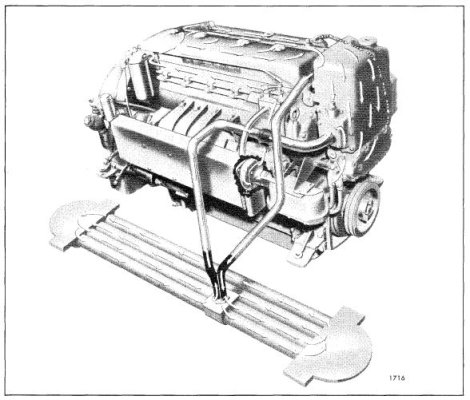
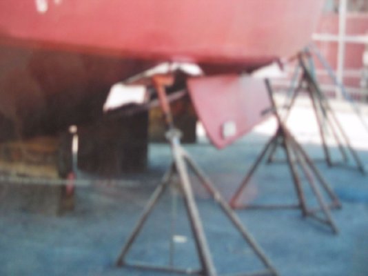
Based upon the pictures, I would be surprised if those fins are keel coolers. They appear to be fins for active stabilizers or some sort of anti-roll device. When you had the boat out of the water, you did not see something that looks like tubular radiator tucked into a pocket of the hull? That is what I would expect and look for, when looking for a keel cooler.

For now, let's assume those are active stabilizers and those are a good thing to have.

Next, go inside and look for the connections to and from those fins. If you see hydraulic ram and hydraulic hoses, they are part of the active stabilizer system and have nothing to do with the cooling system.

We are now back to square 1. One nice thing about square 1, we know where we are.

Have you tried to contact the builder of the boat? IF the company is still around, you can ask some basic questions about the boat. MAYBE then still have some records such as, did it have a keel cooler. Did it have active stabilizers. Perhaps a member of this man's estate can look through the PO's library for some sort of system documentation associated with the boat??

When you haul the boat again or if you are really curious ..... you can do a "short haul". They will keep the boat in the slings as you do a walk around investigating and plot the hull openings. Plot out the location of all the hull openings on two sheets of paper, (put an arrow indicating the pointie end of the boat) one piece of paper for port port side of the bottom and one for starboard side of the bottom. Dont forget those opening on the sides at or above the water line. Make no attempt to identify any of them, beyond the presence and location of the keel cooler. Take pictures too. Personally, I would rely on the drawings..... once you are satisfied with the drawings, put the boat back into the water. Armed with the drawings, drop down into the bilges, find ONE easily recognized hose connected to an easily identified hull opening and system. Let's just start from the stern. Locate it and identify it on the paper. Dont rely on your memory. Document, document, document. Stay on one side, example, the aft port side. When you have documented all hull opening and equated the hull valves to the hull openings on the port side, start over from aft and do it all again for the starboard side, always writing on that paper what you think is correct. You can start over if necessary. Eventually you will have all the hull penetrations identified on paper. Hull openings and hull valve will never move.
Dont worry, for now, about the keel cooler connections. That will sort itself out as we go. After you identify all the hull penetrations on paper ..... you can sit down, stare at the paper and review them in your mind. Please dont be afraid to ask for yard help or another boater.... for a hands-on review.
I know on my Nordhavn, I had more hull penetrations than average boat. The hull valves for the keel cooler were not what one would have expected to find. As I recall, they did not have a handle on the keel cooler hull valves. They were wrench operated, to avoid foolish mistakes, and most definitely meant to be TOTALLY open or factory adjusted. Their settings are not meant to be disturbed. The hoses were much larger in diameter than any other hoses. IF you have adjusted their position return them to the original position. Please tell me, you did not adjust these valves.

The more time you spend on the boat investigating the hull valves, the easier it will be to recognize the hull valves, and their associated systems, either during normal maintenance or emergencies.
Remember, excluding the galley and shower and other sink drains system, there is an 'in and out'. The "in" will be below the water line, the "out" well, that's up for discussion. Most "outs" will be at or above the water line.

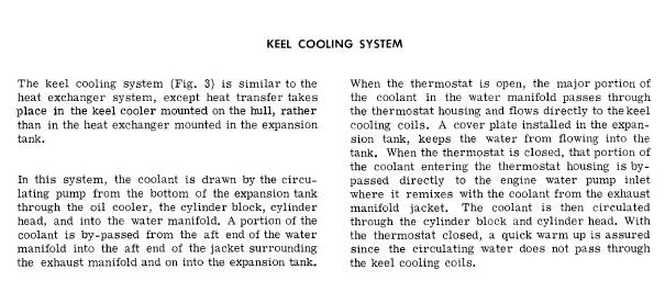
IF you have a keel cooler, it is totally immersed in the water so the 'in' and 'out' connections will be below the water line and connected to the keel cooler.

If I have offend you with this simplistic presentation, please know, that was not my intention. While I was explaining it to you, I was explaining it to myself. Next month I will turn or become 75 years old and I am fast becoming dumber than a rock.

Now I will take questions. There is coffee and donuts at the back of the room.
(Daymn, I hope I explained it properly.) If I mis-said something, or totally wrong, point it out. Some will point out, I did not understand the question.... Perhaps, you did not understand what I wrote. May I thank you for reading this.

Once we get everything back to factory specs, others can discuss adding or removing items from the cooling loop. I did see one very well presented cooling system drawing indicating what he, rightfully, thought would be prefect.

Conclusions and recommendations:
IMO, I seriously suspect you have an active stabilizer system.

Do a quick haul, plot out all the hull openings on paper, and look for keel cooler(s) tucked into pocket(s), or indentations, of the hull. If you cant find them, ask for help from a person who works on boats. "Hey, I am new to this boat and I have been told, I have keel coolers. I cant seem to find them, point them out to me, please."

Ignorance is curable, stupidity..... not so much. Make for the life boats and take your own PFD.

Contrary to what folks say, there actually are 'really dumb questions' but at least, you are smart enough to ask them, expanding your knowledge. The dumbest question is the unasked question.

Once upon a time, I remembered the thickness of the tubes of my Nordhavn keel cooler. Lemme tell you, they were very thin. That is why the keel coolers are protected in hull pockets. (Dont ask me why I thought it was necessary to remember that wall thickness, I forgot why.)

My brain hurts. I'm going to bed.
 
Last edited:
Back
Top Bottom