You are using an out of date browser. It may not display this or other websites correctly.
You should upgrade or use an alternative browser.
You should upgrade or use an alternative browser.
Cummins 6BT5.9M exhaust riser expected life
- Thread starter fryedaze
- Start date
The friendliest place on the web for anyone who enjoys boating.
If you have answers, please help by responding to the unanswered posts.
If you have answers, please help by responding to the unanswered posts.


Firehouse 75, I could not have said it better myself. Jacketed risers are waning in popularity, thankfully, as a failure means almost certain major engine damage. While more challenging to deal with from a heat perspective, dry risers are far safer. More here https://stevedmarineconsulting.com/wp-content/uploads/2014/03/ExhaustSystems170-FINAL.pdf
Also, stainless steel if far from failure-proof, as many have discovered, it's life in seawater exhaust applications is finite. If you are looking for a longer-lived alternative, Inconel. A handful of exhaust fab shops offer it, and the upcharge isn't very large.
Also, stainless steel if far from failure-proof, as many have discovered, it's life in seawater exhaust applications is finite. If you are looking for a longer-lived alternative, Inconel. A handful of exhaust fab shops offer it, and the upcharge isn't very large.
Last edited:
mvweebles
Guru
- Joined
- Mar 21, 2019
- Messages
- 7,237
- Location
- United States
- Vessel Name
- Weebles
- Vessel Make
- 1970 Willard 36 Trawler
Ht.... If you are looking for a longer-lived alternative, Inconel. A handful of exhaust fab shops offer it, and the upcharge isn't very large.
Marine Exhaust of Alabama (Mesa) is one such shop that offers Inconel alloy fabrication.
http://www.mesamarine.com/
Lousy website, but good folks.
Peter
OP
OP
fryedaze
Guru
- Joined
- Sep 4, 2011
- Messages
- 1,722
- Location
- USA
- Vessel Name
- Fryedaze
- Vessel Make
- MC 42 (Overseas Co) Monk 42
Thanks Steve, your knowledge and insights are always appreciated.Firehouse 75, I could not have said it better myself. Jacketed risers are waning in popularity, thankfully, as a failure means almost certain major engine damage. While more challenging to deal with from a heat perspective, dry risers are far safer. More here https://stevedmarineconsulting.com/wp-content/uploads/2014/03/ExhaustSystems170-FINAL.pdf
Also, stainless steel if far from failure-proof, as many have discovered, it's life in seawater exhaust applications is finite. If you are looking for a longer-lived alternative, Inconel. A handful of exhaust fab shops offer it, and the upcharge isn't very large.
OP
OP
fryedaze
Guru
- Joined
- Sep 4, 2011
- Messages
- 1,722
- Location
- USA
- Vessel Name
- Fryedaze
- Vessel Make
- MC 42 (Overseas Co) Monk 42
Soaked in TSP overnight and then wire wheel it. The section of material that they used for the inside of the nozzle may have been cast. None of the other pipe has any degradation. The good pipe is 3" ID with 1/4" wall thickness. The pits on the inside of the nozzle are a concern because I don't know the wall thickness of that section. Inspection of the inside of the mixing nozzle can, shows no degradation of the either the inner or outer walls where the seawater flows through. 


Last edited:
from the pictures you posted, i would think the wall thickness of the inside pipe would be measured from the inner wall to the centerline of the weld. i have no way to judge what that might be without some reference. (like a tape measure across the centerline)
no matter though if you're just going to replace it.
no matter though if you're just going to replace it.
OP
OP
fryedaze
Guru
- Joined
- Sep 4, 2011
- Messages
- 1,722
- Location
- USA
- Vessel Name
- Fryedaze
- Vessel Make
- MC 42 (Overseas Co) Monk 42
Since I removed it I might as well fix it right. The pits are rather deep in some areas. I did a light test and none are thru-wall. I had contemplated putting a 1000f JB Weld paste on the inside but luckily I came back to my senses.from the pictures you posted, i would think the wall thickness of the inside pipe would be measured from the inner wall to the centerline of the weld. i have no way to judge what that might be without some reference. (like a tape measure across the centerline)
no matter though if you're just going to replace it.

Any pics of the spray ring?
Pretty sure the spray ring is on the right. It’ll weld to the tube first, then slip into the housing.
Looking at the housing, the inlet fitting should have been angled, not straight in.
That gets the water swirling around the tube. I guess there could be a diverter inside the housing I can’t see, but you should check for this since you have it all apart.
Looking at the housing, the inlet fitting should have been angled, not straight in.
That gets the water swirling around the tube. I guess there could be a diverter inside the housing I can’t see, but you should check for this since you have it all apart.

The spray ring includes the holes through which water is evenly distributed into the gas stream, it is not shown in any of these photos. It is inside the pipe just upstream of the hose attachment point. See this article for an example opening photo https://stevedmarineconsulting.com/wp-content/uploads/2014/03/ExhaustSystems170-FINAL.pdf
The spray ring includes the holes through which water is evenly distributed into the gas stream, it is not shown in any of these photos. It is inside the pipe just upstream of the hose attachment point. See this article for an example opening photo https://stevedmarineconsulting.com/wp-content/uploads/2014/03/ExhaustSystems170-FINAL.pdf
It’s right there in his last picture. It’s just not welded to the inner and outer pipes yet. It’s modeled after the one he removed and showed early in the thread.
That part sits at the bottom.. It forces the spray to fall down through the exhaust gases for better cooling.
I see. It’s also a place that never drains. Consider a small diameter drain hole at the lowest point.
OP
OP
fryedaze
Guru
- Joined
- Sep 4, 2011
- Messages
- 1,722
- Location
- USA
- Vessel Name
- Fryedaze
- Vessel Make
- MC 42 (Overseas Co) Monk 42
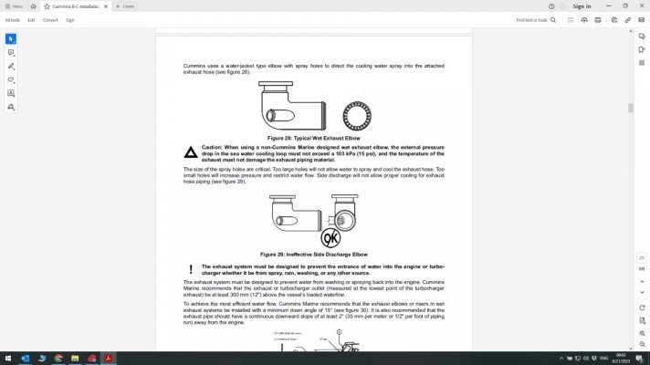
Thanks Steve. This is a 1989 210 HP 6BT5.9M.OK, now I understand. The holes look large. Usually they are about the size of a pencil and there are more of them.
From the Cummins B/C installation manual...
Cummins had cooling issues with these engines. There is no margin and if HX foul a little they have cooling issues. This set up has worked for 33 years. I wouldn't risk smaller holes because it may reduce flow.
If you have ever looked at the size difference between a 210 HP and a 330 or 370. The 210 pumps are tiny.
I have made some of the SBMAR mods to increase flow by increasing fitting sizes and hoses.
OP
OP
fryedaze
Guru
- Joined
- Sep 4, 2011
- Messages
- 1,722
- Location
- USA
- Vessel Name
- Fryedaze
- Vessel Make
- MC 42 (Overseas Co) Monk 42
I had another thought. There is no indication of additional corrosion in the bottom area of that nozzle with no holes. Maybe when the engine is shutdown, everything in that nozzle steams off or evaporatesI see. It’s also a place that never drains. Consider a small diameter drain hole at the lowest point.
Not to say a small hole wouldn't hurt.
Thanks Steve. This is a 1989 210 HP 6BT5.9M.
Cummins had cooling issues with these engines. There is no margin and if HX foul a little they have cooling issues. This set up has worked for 33 years. I wouldn't risk smaller holes because it may reduce flow.
If you have ever looked at the size difference between a 210 HP and a 330 or 370. The 210 pumps are tiny.
I have made some of the SBMAR mods to increase flow by increasing fitting sizes and hoses.
Understood. There is a formula, the collective cross section of the holes has to equal or exceed the cross section of the raw water hose, so there's no guess work. The issue with large holes is you can end up having too much water flow out of lower ones and not enough out of higher ones, especially at low rpm, so there is logic to it. In that case the top section of the hose tends to run hot or even overheat. If you check yours and it works, and hose is "cool" throughout rpm range, then I guess you are good.
I had another thought. There is no indication of additional corrosion in the bottom area of that nozzle with no holes. Maybe when the engine is shutdown, everything in that nozzle steams off or evaporates
Not to say a small hole wouldn't hurt.
If there’s no sign of trouble in that section on the old one I wouldn’t worry about it. You can see exactly where the issues are just by looking at the old one. I would however, passivate the welds before slipping the inner pipe into the housing.
OP
OP
fryedaze
Guru
- Joined
- Sep 4, 2011
- Messages
- 1,722
- Location
- USA
- Vessel Name
- Fryedaze
- Vessel Make
- MC 42 (Overseas Co) Monk 42
Welder finished the repair. It fit perfectly. He returned the liner that had all the pitting. The liner could have lasted another 5 years. There was an area that someone put a JB weld like compound on the pits. The repair held up well. Moving on to Windlass replacement.


Comodave
Moderator Emeritus
- Joined
- Jul 2, 2015
- Messages
- 21,299
- Location
- Au Gres, MI
- Vessel Name
- Black Dog
- Vessel Make
- Formula 41PC
Are you going to wrap it with some insulation? I believe that ABYC calls for no more than 200 degrees and before the water injection it will be more than that. Our last boat didn’t have any and measured over 600. So I added some wrap.
OP
OP
fryedaze
Guru
- Joined
- Sep 4, 2011
- Messages
- 1,722
- Location
- USA
- Vessel Name
- Fryedaze
- Vessel Make
- MC 42 (Overseas Co) Monk 42
There is a vertical station just out of the picture. The rubber exhaust hose is hard against the tiles. The flange at the turbo are not through bolted at the flange. They are clamped. It won't move.Did you do anything about supporting the weight with a brace to the engine or transmission mount?
Ted
OP
OP
fryedaze
Guru
- Joined
- Sep 4, 2011
- Messages
- 1,722
- Location
- USA
- Vessel Name
- Fryedaze
- Vessel Make
- MC 42 (Overseas Co) Monk 42
I am researching removable lagging pads. Not many sources for smaller applications. If I still worked at the power plant I could have one of the insulators make them for me.[emoji4]Are you going to wrap it with some insulation? I believe that ABYC calls for no more than 200 degrees and before the water injection it will be more than that. Our last boat didn’t have any and measured over 600. So I added some wrap.
Comodave
Moderator Emeritus
- Joined
- Jul 2, 2015
- Messages
- 21,299
- Location
- Au Gres, MI
- Vessel Name
- Black Dog
- Vessel Make
- Formula 41PC
I used this from Amazon.
LEDAUT 2" x 50' Titanium Exhaust Heat Wrap Roll for Motorcycle Fiberglass Heat Shield Tape with Stainless Ties
LEDAUT 2" x 50' Titanium Exhaust Heat Wrap Roll for Motorcycle Fiberglass Heat Shield Tape with Stainless Ties
OP
OP
fryedaze
Guru
- Joined
- Sep 4, 2011
- Messages
- 1,722
- Location
- USA
- Vessel Name
- Fryedaze
- Vessel Make
- MC 42 (Overseas Co) Monk 42
I had that Titanium wrap on top of a fiberglass wrap before this job. How many layers do you need when used by itself??I used this from Amazon.
LEDAUT 2" x 50' Titanium Exhaust Heat Wrap Roll for Motorcycle Fiberglass Heat Shield Tape with Stainless Ties
Picture is the fiberglass wrap before I put the Titanium wrap over it.
I put it over the fiberglass because it was making me itchy.

Similar threads
- Replies
- 7
- Views
- 6K
- Replies
- 16
- Views
- 2K