Alternator question for diesel engine

The friendliest place on the web for anyone who enjoys boating.
If you have answers, please help by responding to the unanswered posts.

NWpilot

Veteran Member
Joined
Nov 20, 2020
Messages
59
Vessel Name
Yukon Jack
Vessel Make
30' Tollycraft sedan
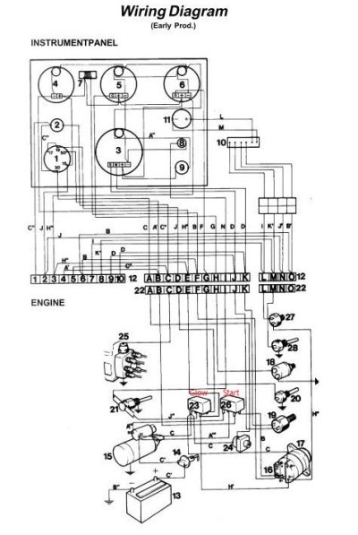
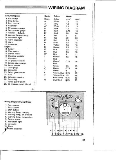
I recently bought a 1979 Tolly with twin Volvo TMD40's. I charged the batteries, did checks, then started the engines and ran them for less than 10 minutes. I then discovered that between the previous survey (or he missed it) and now the charging wires had overheated and melted the insulation from the alternator to the starter. So had the ground wire from the alternator.

The original alternators were 50 amp and the owner had replaced them within the last few years with Leece-Neville 105 amp units. He didn't attach the "sense" wire to the alternator and simply routed it to the instrument panel from the starter relay.

I'm replacing all the damaged wiring with heavier a gauge but I'm really bothered that I haven't found a smoking gun, or why the failure. The original charge circuit was 9 gauge and i'm replacing it with 8 gauge.

Is it possible that the wiring circuitry including the relays are just not rated for 105 amps and that burned the wires up? How does the alternator adjust charging voltage without a sense wire?

Any any all help is appreciated.
 
Not real sure what alternator you have but the HD 130 and 160 Leece Neville are internally regulated and only need about a #4 or #2 wire to the battery. These are really common in the heavy equipment and truck world and a couple have found their way into my boat. Very good high output units for a reasonable price.
 
How long is the run? 100+ amps in 8 gauge would not be my preference.
 
The 105 amp alternator should have #6 between the alt output terminal and the starter. The # 8 wire max is 85 amps in the ER IF it has 105*C insulation. No wonder it melted.
 
And the output wire should go directly to the battery bank, not through the starter.
 
As noted above #9 (a weird size in the US) will only handle about 70 amps. Replace it with at least #6 gauge, and larger would be better to limit voltage drop.

Lots of engine alternator outputs go to the positive starting lug. That lug acts as a heavy buss as the starter cable is very large gauge, 2/0 usually. I assume that the negative connects to the block which also acts like a heavy buss.

The voltage sense wire lets you connect it to the battery so the alternator regulator can sense what voltage the actual battery is getting and regulate it accordingly. Otherwise the regulator will regulate to its terminal output voltage. The batteries will see a lower voltage due to wire losses and won't charge as well.

Upgrading alternators without upgrading wiring is a common mistake.

David
 
I went to bed and woke up to a lot of questions.

The current alternators are Leece-Neville 8MR2401 UA with a BRG 2043 regulator. I have researched their site for wiring info and found very little. Apparently they are internally regulated.

Wiring goes from the alternator to the glow relay where it supplies power to the ignition switch and glow plugs and then continues on to the battery cable lug on the starter. The path to the starter is about 6' - 8' total run. The wiring was originally 9 gauge for all of this circuitry (Volvo) and I went to 8 gauge before discovering the alternators were 105 amp.

David's comment hits home with me "Upgrading alternators without upgrading wiring is a common mistake." The previous owner was pretty careless about maintenance and he lived in Calif. and only came up here to fish, so limited time for working on the boat.

I see my choices as:

Leave the existing wiring for the glow and ignition and replace the run on to the starter with a 6 gauge or larger going straight from the alternator to the battery, about 8'.
or
Replace the alternator with one in the 50 - 70 amp range. I've read that cutting the circuitry on an alternator resulting in no where for the current to go will fry an alternator. I haven't been able to test it to see if it's still working.

Thanks guys for the help. Any thoughts on the choices?

Chas
 
I Googled BRG2043 and found an item that told me it is actually 8RG2043, FWIW.

I am a little confused by the statement "Wiring goes from the alternator to the glow relay where it supplies power to the ignition switch and glow plugs and then continues on to the battery cable lug on the starter." and the subsequent statement about replacing the run from the ignition switch and glow plugs to the starter with #6 gauge.

It all has to be replaced with #6- from the terminal on the alternator to the big starter lug. That is by far your cheapest solution. And like I said, also check the negative wire size unless the alternator relies on its case to ground to the engine block.

David
 
David,
Those were the only numbers I pulled off the regulator except Sales # 105-280.

The glow relay is used as a terminal where the branch to the starter and a 9 gauge wire through a breaker to the ignition panel are all attached to the same terminal lug. Power to the start relay is fed from a 13 gauge wire attached to the starter. I believe this arrangement is so you can power up the glow plugs for 30 seconds before starting.

I know it's confusing as it's got me confused. I have the schematic and can post it if you want. Maybe you can check my assumptions.

I proposed going straight from the alt to the battery to reduce voltage drop.

In fact, I will post the schematic. Give me a few minutes.

Thanks again for your help.

Chas
 
OK, here's what I'm working with. The "C" wires between the alternator and the starter are the ones that fried, plus the alternator ground which isn't shown.
 

Attachments

  • Instrument Wiring 01A.jpg
    Instrument Wiring 01A.jpg
    82.4 KB · Views: 56
  • Instrument Wiring 02.jpg
    Instrument Wiring 02.jpg
    135.8 KB · Views: 34
That is a weird route for an alternator output. I would just wire #6 gauge from the alternator output terminal to the starter lug. The glow plug will get power from the starter lug.

David
 
Thanks David.
I'm going to finish wiring it up tomorrow and see how it goes.
 
Any thoughts on the choices?

Chas

I know little about your specific alternator, but ask only this:
Where is the smart regulator? I haven't heard of any internally regulated alternator that puts out high amperage in a "smart" three stage way without a proper external regulator. My own boat started life with Volvo 50 amp alternators on both engines. I changed one to a higher output when I put in a smart regulator, the "Next Step" from Ample Power in Seattle. I have thought about bumping up the second alternator to high output, but haven't pulled the trigger on that just yet, as it is only connected to the start battery.

In improving the output from 50 to 120 amps, with 3 stage regulation, I know I have improved charging on the house side. I know the charging profile of my regulator. I also know that the original internally regulated alternator was totally unsuitable to manage the house bank, as it would reduce output far too quickly to ever replace a daily load, especially if the fridge is not efficient.
 
****** How does the alternator adjust charging voltage without a sense wire?*******

Many/most stock alternators are built with INTERNAL regulators which take the reading from the inside of the alternator.

Your alternator is most likely of this type.

The system can be moded with some caveats which I won't go into here but could be explored in a different thread.
Get comfortable with what you have now and the needed repairs first.
 
Keith,

I don't have a smart regulator as far as I know. I wasn't even familiar with an internal regular. I'm old school. It is claimed that the Leece-Neville is a two stage, bulk and absorption, with no temp control.

Like I stated, the previous owner just upgraded the alternators and left everything else alone. I've decided to install a new charge wire, as I stated, and test the alternator. If it's dead due to the wiring burning up I'll assume the other one is dead also and I can start from scratch.

I've a lot to learn about battery maintenance.

Chas

C-Lectric has far greater knowledge of this subject than I do, so I suggest following his advice. Then, when things have settled down, you can explore the rest of your charging system at leisure.
 
Leece Neville are internally regulated and only need about a #6 or #4 wire to the battery(depending on their Location). Your issue was probably caused buy undersized wiring and most likely a drained batteries (that required full current from the alternator). a good battery will draw full current for seconds then drops maintenance current level.
 
I installed the same alternator on my boat 5 years ago. It will charge at 105-111 amps (Bulk charge) until the regulator sees 14.5 volts (adjustable with the tiny tweeker slot) then maintains voltage constant there (Absorb charge) with amps dropping as SOC rises. There is no Float Mode.

We have not had any signs of overheating of the alt coils or wiring (6 gauge). We typically run 3-8 hours a day when traveling running 6-6VDC golf cart batteries down overnight to 50-70% SOC with refrigeration.
 
OK, so I spent Monday and Tuesday running a new #6 charge wire to the starters and beefed up the grounds also. I started the port engine and measured 14.2 volts at the alternator and was actually surprised it worked after the meltdown. The starboard engine would turn over but wouldn't start. I suspect I have some more fried wires to find and repair on that side.

I'm thinking the theory about upgrading the alternators without upgrading the wiring is my problem. You could limp along without too much damage until that time the batteries were very discharged and used the alternators to charge them. When I took possession the Xantrex charger was toast. Meanwhile a marina had worked on the boat and I think they jumped the batteries to start it and drive it back to the moorage. I believe that's when the final damage occurred and the wires separated.

The marina charged the previous owner $2500 to diagnose a restriction the the fuel line for the starboard fuel tank and tell her the hydraulic steering needed the lines replaced. The boat has an autopilot and rather than turn it off they installed a bypass hose on the steering cylinder. I've since removed the bypass and refilled the system with oil and it steers fine.

Off to find that pesky short.

Chas
 
Yes, many have the alternator output wired through the starter. Doing so works but that does not make it the better choice especially since, in this case, a new wire run is being considered. Here is a link to Ron Collins' MarineHowTo website where he explains why the alternator output should go directly to the battery bank. The reasons are not inconsequential.

https://marinehowto.com/alternators-voltage-sensing/
As noted above #9 (a weird size in the US) will only handle about 70 amps. Replace it with at least #6 gauge, and larger would be better to limit voltage drop.

Lots of engine alternator outputs go to the positive starting lug. That lug acts as a heavy buss as the starter cable is very large gauge, 2/0 usually. I assume that the negative connects to the block which also acts like a heavy buss.

The voltage sense wire lets you connect it to the battery so the alternator regulator can sense what voltage the actual battery is getting and regulate it accordingly. Otherwise the regulator will regulate to its terminal output voltage. The batteries will see a lower voltage due to wire losses and won't charge as well.

Upgrading alternators without upgrading wiring is a common mistake.

David
 
THe alternator output is run to the starter motor + terminal as a one size fits all connection point and it done with the assumption that the main battery set will be the start/primary engine battery. Since the engine when it leaves the factory is not in a boat the alt. must be connected somewhere and this is a good place to do so.

This works Ok for many applications untill we come along and install a far larger battery set, house, that needs a lot more use, charging/discharging than the engine battery.

Then WE must make the changes needed. Just do not forget to make provision for the starter battery to get a recharge.

On mine I added a 150A alt., ran the output directly to the HOUSE battery with a 2/0 wire. The neg. also comes back directly to the alter. on a 2/0 wire.

Were it me even with a 100A alt. I would use a #4, not a #6, to and from the battery directly.
 
Last edited:
I purchase a 100 amp Leece Neville built by Rob at How to marine. I also purchase the Wakespeed 100. Both work great. There are two wires on the alternator one for positive and one for ground #4 gauge to the starter 2/0 cables. A smaller wire goes to the field coil which the regulator controls to provide the proper smart charging. Bulk to14.8 volts, absorb at 14.6 and float a 13.4. Voltage varies a little depending upon battery type. You can choose a 50 to 100 amp max output (It works though a 2 hour cycle. There is also a much smarter Wakespeed 500 also better price that does an even better job of output control. There are also temp sensors for the battery and alternator on both. I also have a 160 amp L-N on the opposite engine with a Ample Power regulator- work great also, but they are out of business. Rob also sells Balmar equipment
The old L-N 50amp alternator internally regulated, only charged to 13.8 volts -- never fully charging a battery.
 
Last edited:
"The old L-N 50amp alternator internally regulated, only charged to 13.8 volts -- never fully charging a battery."

Most of the new large frame alts at the engine store require an external regulator , as well as a directional fan and a pulley of your choice. Go dual if there is room.

These are the best deal for a diesel 135A for under $150. added parts are extra.

Superb reliability .
 
How does the dash amp meter work if the alternator output goes direct to battery?

It doesn't, maybe.

If the old meter is of sufficient range AND it is an external shunt type then the shunt simply needs to be moved so it is again in the output wire from the alternator.

Often when these changes are made the change is driven by a more powerfull alternator to maintain a larger battery setup which frequently means the stock ammeter no longer has the range of reading to be of any use and may become dangerous if left in the circuit.

In that case a greater range ammeter/shunt set must be used if you still want to read the alternator output. Or use a Hall Effect coil type ammeter.
 

Latest posts

Back
Top Bottom