2 Alternators - Single Engine???

The friendliest place on the web for anyone who enjoys boating.
If you have answers, please help by responding to the unanswered posts.

mvweebles

Guru
Joined
Mar 21, 2019
Messages
7,218
Location
United States
Vessel Name
Weebles
Vessel Make
1970 Willard 36 Trawler
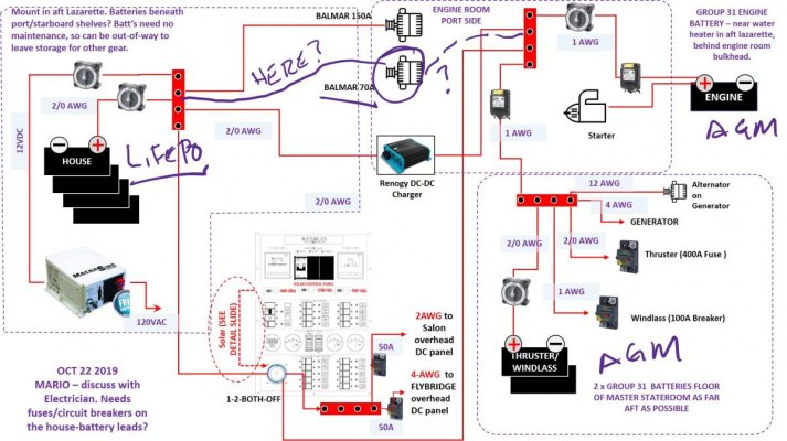
Folks - could use some good thinking on whether I should add a second alternator or not; and if I do, how it should be run.

BACKGROUND (see DC diagram attached):

  • Weebles: Willard 36 with single Perkins 4.236 (80hp).120VAC and 12VDC (no 240VAC, no 24VDC)
  • Battery Banks:
    • 600AH Lithium house
    • 2x group 31 AGM for gen start, thruster, and windlass. Note, gen does not have dedicated battery. Frankly, I am out of room.
    • 1x group 31 AGM for engine start
NOTE - there is a Renogy DC-DC converter between the Lithium batteries and the AGM/G31s
  • Charging Sources (all new):
    • 150A Balmar regulated alternator (primary)
    • 70A Balmar regulated alternator (secondary - sort of a freebie - question is should I install this, and if so, where/how?)
    • 15A alternator on the generator (useless?)
    • 800kw solar panels
    • 3.2 kw Magnum hybrid charger (shore power or gen set)
EXAM QUESTIONS:

  • See hand-written notes on attached diagram. I already have the two Balmar alternators. Q: Should I install the second one? Engine is out of the boat and sitting on a bench, so welding a bracket is pretty easy at this point.
  • Q: If I add the second Balmar, where should I run the 70A hot?
    • Same bus-bar feeding the House bank as the 150A making 220A
    • Different bus bar feeding the G31s AGMs?
    • Don't bother with the second Balmar?
    • Something else?
    Q: What to do with the weeny output of the 15A alternator on the NL 6kw generator? Anything?
  • Other comments/observations are welcomed. Attached wiring diagram has been changed a bit, but for purposes of this post, is correct for the DC wiring.
Thanks in advance!

Peter
Mar 3 Wire DIagram (DC).jpg

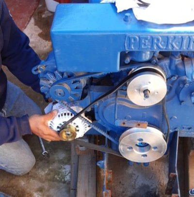
Weebles 2x Alternator.jpg
 
I had a very similar setup on my last boat, and ended up reworking it to be pretty much like what you are contemplating. I liked it so much, I'm doing it again on the new boat.


The setup was a 190A and and 85A alternator on the main engine. They were originally wired with the 190 to the house bank and the 85 to the start bank, each with it's own external regulator.


90% of the time the 85A alternator was doing nothing, so I rewired so both the 190 and 85 went to the house bank for a combined 275A output.


I also controlled both of them together from a single external charge regulator. This may seem counter intuitive, and lots of people will tell you you can't do it, but it actually works exceptionally well. Both alternators are driven by the save Field output from the regulator, and each drives to the same proportion of it's full output capacity. When the controller commands half field, or half output, each alternator puts out half of it's capacity. So the 190 puts out 80A, and the 85 puts out 42.5A. At full commanded output, they both put out full power. So it's always naturally balanced to each unit's capacity.


To charge the start bank, I used a DC to DC charger, Mastervolt in my case.


And my generator I left alone and it charged the generator start bank.


If you search my blog, there is an article on it.
 
Peter, I think you're making a big mistake. You absolutely don't want to run both belts over the crankshaft and the water pump pulleys. Any discrepancy between the circumferences or the 2 water pump pulleys means one belt is moving faster than the other. The same situation applies to the crankshaft pulleys. When you combine these 2 belts moving at different speeds, they will fight each other and one will die.

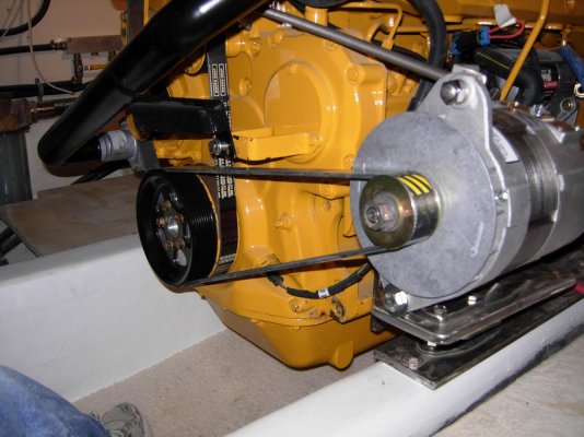
You want to run the larger alternator with the serpentine belt only off the crankshaft pulley. The reason for doing this is that the larger alternator puts the most load on the crankshaft pulley. The greater the percentage of the circumferences of the pulley the belt touches, the better the traction (grip) the belt has on the pulley. This can be the difference between belt slippage and wear or not. In your picture, the very small alternator pulley has less than 1/3 of the circumference in contact with the belt. If you run that alternator only off the crankshaft pulley, the contact doubles.

Your 2nd alternator belt configuration should look like this for best belt traction:

DSCN1035.jpg

I'll comment on the wiring in another post.

Ted
 
Last edited:
You'll have a well-underutilized 70A externally regulated alternator to your G31 start bank that provides a good Plan B in the event of alternator #1 taking a nose dive...as long as you reprogram from LifePO4 to AGM.

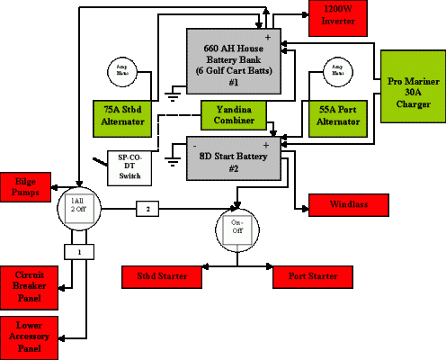
My boat's similarly configured, but I have twin 4.236's and all LA batts. Here's an old schematic that has been upgraded in components. I now have a 55A shore charger and a Balmar ER 120A 12V going to the house 660A. Unfortunately, I found out too late that needed to add a blower to keep it within temp specs...135*F. DAMHIK!!!

:facepalm::banghead::facepalm:

(Thanks to CMS for helping me decipher the root causes of my Balmar meltdown.)
 

Attachments

  • Schematic.gif
    Schematic.gif
    13.5 KB · Views: 50
Last edited:
Peter, I think you're making a big mistake. You absolutely don't want to run both belts over the crankshaft and the water pump pulleys. Any discrepancy between the circumferences or the 2 water pump pulleys means one belt is moving faster than the other. The same situation applies to the crankshaft pulleys. When you combine these 2 belts moving at different speeds, they will fight each other and one will die.

You want to run the larger alternator with the serpentine belt only off the crankshaft pulley. The reason for doing this is that the larger alternator puts the most load on the crankshaft pulley. The greater the percentage of the circumferences of the pulley the belt touches, the better the traction (grip) the belt has on the pulley. This can be the difference between belt slippage and wear or not. In your picture, the very small alternator pulley has less than 1/3 of the circumference in contact with the belt. If you run that alternator only off the crankshaft pulley, the contact doubles.

Your 2nd alternator belt configuration should look like this for best belt traction:

View attachment 100095

I'll comment on the wiring in another post.

Ted
Ted - really good observation. I had planned to have the second alternator moved to other side of engine to equalize side loading, but never occurred to me the belts should not share a similar path.
 
90% of the time the 85A alternator was doing nothing, so I rewired so both the 190 and 85 went to the house bank for a combined 275A output.

If you search my blog, there is an article on it.

For others, I believe this is the blog post TT references.

Note that he describes consulting with Balmar on the ultimate wiring to use a single regulator for the two alternators, only possible as he going to the same battery bank with the field/positive. I also note that the cable from the alternator to the battery bank will need to be appropriately sized for the increased amperage.

Many thanks TT -

Peter
 
Last edited:
Ted - really good observation. I had planned to have the second alternator moved to other side of engine to equalize side loading, but never occurred to me the belts should not share a similar path.


Another option would be to change the pulley on the old alternator and use a single serpentine belt for everything. Then perhaps add a spring tensioner.
 
For others, I believe this is the blog post TT references.


Note that he describes consulting with Balmar on the ultimate wiring to use a single regulator for the two alternators, only possible as he going to the same battery bank with the field/positive. I also note that the cable from the alternator to the battery bank will need to be appropriately sized for the increased amperage.


Many thanks TT -


Peter


Right, if you do as I describe, the alternators and regulator have to go to the same battery bank. And the alternators need to be on the same engine.
 
Another option would be to change the pulley on the old alternator and use a single serpentine belt for everything. Then perhaps add a spring tensioner.

I would avoid using one belt. The tension required for the higher output alternator is significantly greater than the other alternator and the water pump. One only has to look at the required belt size to realize the the additionally required power. While the water pump and old alternator may handle the extra side load from the tension, there isn't a compelling reason to do it. Finally, you will want to spin the second alternator faster for better cooling as it will be running at full output with an external regulator until the battery is charged. Too accomplish this, you wand to use the largest crankshaft pulley and smallest alternator pulley. I also think it's a mistake from a wear standpoint to change the water pump speed unnecessarily. The picture of my setup above, gives the best performance for the 2nd alternator while maintaining the proven performance of the original engine configuration.

Ted
 
Right, if you do as I describe, the alternators and regulator have to go to the same battery bank. And the alternators need to be on the same engine.


I only have one engine, so not a problem. But curious, why do they have to be on the same engine? What happens if one of the alternator fails or a belt breaks?


Peter
 
Just bear in mind that your Balmar 150A 6-Series should be set up, using belt load manager, to not exceed max safe temp specs. The Alt temp sensor is great back up insurance policy to belt load manager.

No small frame alternator, unless externally rectified, is "constant duty". Charging LFP is constant duty stuff and, typically speaking, a large frame alternator is going to net you more of the "rated" output than a small frame unit will. Reduce the output ahead of time using belt load manager and your alternator will thank you for it. Another alternative is to use the Wakespeed WS500 regulator and you can now set the alternator to run based off a maximum specified temperature.

LFP likes to eat alternators for lunch.
 
Last edited:
CMS - thanks so much. Have PM'd you for more info on the Wakespeed regulator. BTW - I was introduced to MarineHowTo on this forum and found it incredibly helpful. Wish I had found you earlier in my outfitting process.


Ted/OCDiver - the pulley setup you have makes sense. I see you have dual serpentine pulley/sheaves on your main crankshaft. Any recommendations on sourcing these sheaves? I purchased the three sheaves and serpentine belt from TAD so they came as a set and assume its engineered properly as they seem to work closely with Balmar, but makes best sense to put the small alternator there, and run large alternator direct, but need sheave. Thoughts?
 
Regarding wiring, I would recommend what I did on my boat. First, I don't think the 70 amp alternator will live a long life running high output with an external regulator, it wasn't designed for that. Secondly, I believe in independent redundancy for a single engine electrical system (especially if the generator is going to share a battery).

I would wire the 70 amp alternator to the start battery with nothing else. This is reliability through simplicity. I would wire the 2nd alternator to the house battery bank with an external regulator. Reduce the number of electrical components as much as possible to reduce failure points. The cabling between the 2 alternators and batteries should be separate with the engine block being a shared common negative terminal. (Note: because of the amperage of my 220 amp 2nd alternator, I ran a 3/0 negative cable from the alternator frame to the negative buss. I felt a direct path of tinned copper was a better choice than going through several steel and cast iron components that were bolted together. ) The final component I would add is a switched cable from the house battery buss to the engine starter. This will allow you to join the 2 battery systems to overcome the failure of a battery or an alternator. My original setup utilized a Sterling external regulator. When it failed, eliminating the second alternator output, I was able to handle house bank operating loads while underway by simply combining the battery banks. After the second Sterling regulator failure, I stitched to a Balmar external regulator.

Ted
 
Ted
Noting your switched cable comment, I found the parallel switch to be helpful when one of my alternators began acting up.

What a great thread with some spot on contributors.
 
Ted/OCDiver - the pulley setup you have makes sense. I see you have dual serpentine pulley/sheaves on your main crankshaft. Any recommendations on sourcing these sheaves? I purchased the three sheaves and serpentine belt from TAD so they came as a set and assume its engineered properly as they seem to work closely with Balmar, but makes best sense to put the small alternator there, and run large alternator direct, but need sheave. Thoughts?

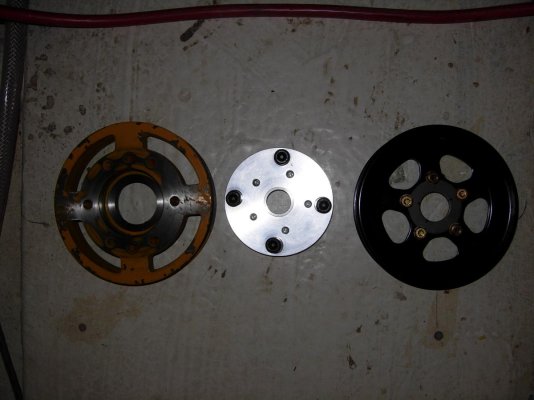
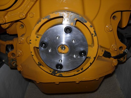
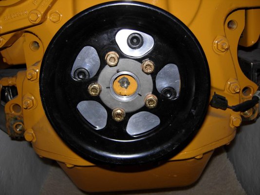
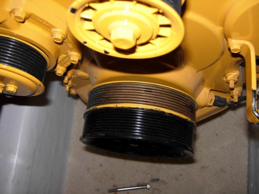
I bought a second pulley from John Deere (although the source doesn't matter). Took the crankshaft pulley and 2nd pulley to a machine shop. They faced the first pulley; made an adapter to go between the 2 pulleys; and attached the second pulley. The below pictures show the sequence. The black counter sunk cap screws attach the adapter to the crankshaft pulley. The gold colored bolts attach the 2nd pulley to the adapter. After attaching the adapter to the crankshaft pulley, they faced the adapter to make it as true to the 1st pulley as possible. When the assembly was complete, they spun the setup at 3,000 rpm in a lathe to check trueness. It's perfect, and almost zero space between the pulleys! Here is the dry fit up.

DSCN1025.jpg

DSCN1026.jpg

DSCN1027.jpg

DSCN1028.jpg

DSCN1030.jpg

Ted
 
Last edited:
On the starting battery layout, I see no issue with the generator sharing with the windlass and thruster. Just make sure that both the engine and generator have a battery switch layout that allows either one to be started from the other's start battery.
 
I bought a second pulley from John Deere (although the source doesn't matter). Took the crankshaft pulley and 2nd pulley to a machine shop. They faced the first pulley; made an adapter to go between the 2 pulleys; and attached the second pulley. The below pictures show the sequence. The black counter sunk cap screws attach the adapter to the crankshaft pulley. The gold colored bolts attach the 2nd pulley to the adapter. After attaching the adapter to the crankshaft pulley, they faced the adapter to make it as true to the 1st pulley as possible. When the assembly was complete, they spun the setup at 3,000 rpm in a lathe to check trueness. It's perfect, and almost zero space between the pulleys! Here is the dry fit up.

I purchased the 150A Balmar along with serpentine belt kit from TAD so assume they are compatible, but since I am running a second alternator, will run the 70A with replacement serpentine kit. 150A as a solo-belt off second 6-groove sheave. But I also have a third belt-driven load: hydraulic pump for stabilizers. These were originally run off a v-belt, but since the pump is new, might make sense to just run it as a 6-groove belt too. Would mean a triple-sheave on the crank shaft. Now, the old setup had 4-5 v-belt sheaves for stuff that OP had installed and is long gone, but still, wondering if that's just too much to hang off the crankshaft unsupported?

Was hoping there was a bolt-on sheave setup. Looks like there are replacements for v-belt. Have not found same for 6-groove. But machining a new one may not be too bad. Thanks -

Peter
 
With 3 belts on the front, I'd just try to mount stuff to put the highest loaded belts closest to the engine.

Or, use idlers for better belt wrap and put some of the items on a single belt like the serpentine setup on most modern cars. A 6 or 7 rib belt with good wrap on the pulleys can transmit quite a bit of power without needing excessive tension.
 
On the starting battery layout, I see no issue with the generator sharing with the windlass and thruster. Just make sure that both the engine and generator have a battery switch layout that allows either one to be started from the other's start battery.

Hmmmm, thruster and windlass amp draws are pretty large in comparison to most small genset needs. Interesting battery choices taking into account space, cable runs and DC motor requirements.
 
Hmmmm, thruster and windlass amp draws are pretty large in comparison to most small genset needs. Interesting battery choices taking into account space, cable runs and DC motor requirements.

Agreed. But it's unlikely that the thrusters or windlass would be in use while cranking the genset (and it's plenty of battery to start the gen). So it's functionally fine. I'd rather see those loads combined with genset start than engine start, as I prefer having engine start power independent and with no other loads on it to minimize the risk of it not being there (and needing to switch to backup starting power).
 
Agreed. But it's unlikely that the thrusters or windlass would be in use while cranking the genset (and it's plenty of battery to start the gen). So it's functionally fine. I'd rather see those loads combined with genset start than engine start, as I prefer having engine start power independent and with no other loads on it to minimize the risk of it not being there (and needing to switch to backup starting power).

By far, most challenging part of refitting a 36-foot boat - especially a Willard 36 that is not exactly a large 36-footer, is fitting 10-lbs of potatoes into a 5-lb sack. Many of the attributes that make it a good sea-boat work against it for stores: low decks. Back in the 1960s, generators were not common, certainly not watermakers and other spacious attachments.

I fully understand not having a dedicated gen-start battery is not a best practice. My thinking is multiple charging sources make it an acceptable trade-off: 800W solar, two alternators, a third 15A alternator off the Generator that will go to the 2xG31 AGM bank, and a DC-DC charger from house bank. If it proves otherwise, I'll have to make some choices and find a place for yet another battery and cabling. But I do agree it's a compromise I was willing to make for gen start, but rslifkin states, not one to make for engine-start (which is dedicated).

Thanks for the comments.

Peter
 
Last edited:
I fully understand not having a dedicated gen-start battery is not a best practice. My thinking in making the tradeoff is with multiple charging sources it's an acceptable trade-off (800W solar, two alternators, and DC-DC charger from house bank). If it proves otherwise, I'll have to make some choices and find a place for yet another battery and cabling. But I do agree it's a compromise.

I don't really see your choice of gen start power as an issue. My gen shares a battery with one of my engines, for example. As long as you can start the gen and engine from 2 different power sources, you're in good shape. And the windlass and thruster wouldn't typically be used without the engine running, so power drain on those batteries isn't a concern.
 
I purchased the 150A Balmar along with serpentine belt kit from TAD so assume they are compatible, but since I am running a second alternator, will run the 70A with replacement serpentine kit. 150A as a solo-belt off second 6-groove sheave. But I also have a third belt-driven load: hydraulic pump for stabilizers. These were originally run off a v-belt, but since the pump is new, might make sense to just run it as a 6-groove belt too. Would mean a triple-sheave on the crank shaft. Now, the old setup had 4-5 v-belt sheaves for stuff that OP had installed and is long gone, but still, wondering if that's just too much to hang off the crankshaft unsupported?

Was hoping there was a bolt-on sheave setup. Looks like there are replacements for v-belt. Have not found same for 6-groove. But machining a new one may not be too bad. Thanks -

Peter

When considering adding hydraulics for a bow thruster, my final choice was to direct drive it off My ZF 280.1 transmission. ZF makes an adapter assembly that bolts the hydraulic pump to the transmission. 2nd choice was to direct drive it off the crankshaft on the front of the engine. This required a little more fabrication, but is commonly done on commercial boats and most cement mixer trucks. Ultimately I switched the bow thruster to 24 volt and saves probably $6K.

In order of preference, I would direct drive the pump off the crankshaft 1st, run the pump and 150 amp alternator off an 8 groove serpentine belt (this will require atleast 1 idler pulley to ensure proper belt contact with all pulleys) (this will also be tough to fabricate and align all the pulleys) 2nd, and have 3 belt configurations off the crankshaft would be 3rd.

Ted
 
Just bear in mind that your Balmar 150A 6-Series should be set up, using belt load manager, to not exceed max safe temp specs. The Alt temp sensor is great back up insurance policy to belt load manager.

No small frame alternator, unless externally rectified, is "constant duty". Charging LFP is constant duty stuff and, typically speaking, a large frame alternator is going to net you more of the "rated" output than a small frame unit will. Reduce the output ahead of time using belt load manager and your alternator will thank you for it. Another alternative is to use the Wakespeed WS500 regulator and you can now set the alternator to run based off a maximum specified temperature.

LFP likes to eat alternators for lunch.

I learned the hard way that alternator cooling is paramount. My Alt temp sensing cable was connected by the installer to the ground lug. In most cases, that's the proper location. On my 621-series Balmar, the ground lug is offset on an L bracket from the case for tight mount confines and does not provide a good point from which to measure the alt temp. My alternator fried itself trying to put out max juice at extended high idle speeds during photo shoots without adequate cooling or temp protection.

CMS/Rod pointed out this issue with these 6-series alternators and advised me about a small (#10?) threaded hole on the frame that is intended to provide the temp sensing connection. He also advised me on the Belt Manager settings and told me that some have to revert to a dedicated blower to keep the alt temp within limits.

Sure enough, Rod was right again! After having the Balmar rebuilt locally, I moved the temp sensor to the appropriate mount location and the regulator ramped down the output as the temp reached 135*. In the following weeks, I added a dedicated blower to the Balmar and now, all is well.

Over time I've learned that it's all about balancing power, loads and cooling. A HUGE THANKS to Rod/CMS for his help in identifying the problem and suggesting practical, sound solutions to the issue. Hat tip to CMS! :flowers:
 
I also added a second alternator to my John Deere 6068 engine. I wanted a second belt, and contacted two JD dealers and was told that there was no front pulley available for that engine. So I had a machine shop make a round plate and a stub shaft bolted to the vibration damper. I attached a pulley that I bought at an Industrial supply. The second alternator is 70A and normally is connected only to the start battery. I also added a second regulator, and a crossover switch that I can close if either alternator malfunctions.
 
When considering adding hydraulics for a bow thruster, my final choice was to direct drive it off My ZF 280.1 transmission. ZF makes an adapter assembly that bolts the hydraulic pump to the transmission. 2nd choice was to direct drive it off the crankshaft on the front of the engine. This required a little more fabrication, but is commonly done on commercial boats and most cement mixer trucks. Ultimately I switched the bow thruster to 24 volt and saves probably $6K.


In order of preference, I would direct drive the pump off the crankshaft 1st, run the pump and 150 amp alternator off an 8 groove serpentine belt (this will require atleast 1 idler pulley to ensure proper belt contact with all pulleys) (this will also be tough to fabricate and align all the pulleys) 2nd, and have 3 belt configurations off the crankshaft would be 3rd.


Ted


If direct drive like this is possible, I too would highly recommend it. I’ve seen too many boats with problems with belt driven pumps.
 
Not sure

Folks - could use some good thinking on whether I should add a second alternator or not; and if I do, how it should be run.

BACKGROUND (see DC diagram attached):

  • Weebles: Willard 36 with single Perkins 4.236 (80hp).120VAC and 12VDC (no 240VAC, no 24VDC)
  • Battery Banks:
    • 600AH Lithium house
    • 2x group 31 AGM for gen start, thruster, and windlass. Note, gen does not have dedicated battery. Frankly, I am out of room.
    • 1x group 31 AGM for engine start
NOTE - there is a Renogy DC-DC converter between the Lithium batteries and the AGM/G31s
  • Charging Sources (all new):
    • 150A Balmar regulated alternator (primary)
    • 70A Balmar regulated alternator (secondary - sort of a freebie - question is should I install this, and if so, where/how?)
    • 15A alternator on the generator (useless?)
    • 800kw solar panels
    • 3.2 kw Magnum hybrid charger (shore power or gen set)
EXAM QUESTIONS:

  • See hand-written notes on attached diagram. I already have the two Balmar alternators. Q: Should I install the second one? Engine is out of the boat and sitting on a bench, so welding a bracket is pretty easy at this point.
  • Q: If I add the second Balmar, where should I run the 70A hot?
    • Same bus-bar feeding the House bank as the 150A making 220A
    • Different bus bar feeding the G31s AGMs?
    • Don't bother with the second Balmar?
    • Something else?
    Q: What to do with the weeny output of the 15A alternator on the NL 6kw generator? Anything?
  • Other comments/observations are welcomed. Attached wiring diagram has been changed a bit, but for purposes of this post, is correct for the DC wiring.
Thanks in advance!

Peter
View attachment 100087

View attachment 100088


Everyone jumped in to tell you how to do it. I am wondering why a 150 amp alternator by itself is not enough. What problem are you trying to solve? During the day, you solar is adding about 20 amps/hour.

In my case, I have a 900 amp firefly batter bank powered by to 110 amp Alternator’s controlled by Balmar regulators. My 24 volt bow thruster is only charged when I am on shore power or connected to gen set. My two generators have separate batteries.

Are you running so much equipment on the boat that the 150 amp alternator can’t keep up? Have you arrived at destination to find depleted batteries or have you cooked the alternator? I mean Alternator’s are cheap. Why go to all this work?
Think you missed that the 70 amp was the original and the 150 amp may not fit there or may require substantial changes to the crankshaft pulley harmonic balancer to accommodate the required belt change.

Personally, I like the concept of redundant alternators for a single engine cruising boat.

Ted
 

Latest posts

Back
Top Bottom