Why won't the winch run?

The friendliest place on the web for anyone who enjoys boating.
If you have answers, please help by responding to the unanswered posts.
Joined
Jul 3, 2016
Messages
1,441
Location
USA
Vessel Name
Escape
Vessel Make
Mariner 37
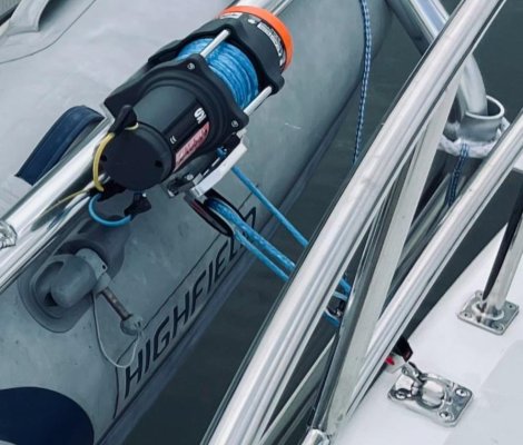
I installed a Dinghy Butler system to keep our tender out of the way while underway. The physical install went great and the electrical system is pretty straightforward. I powered it up last September with a temporary connection to our generator start battery and the system worked just fine.

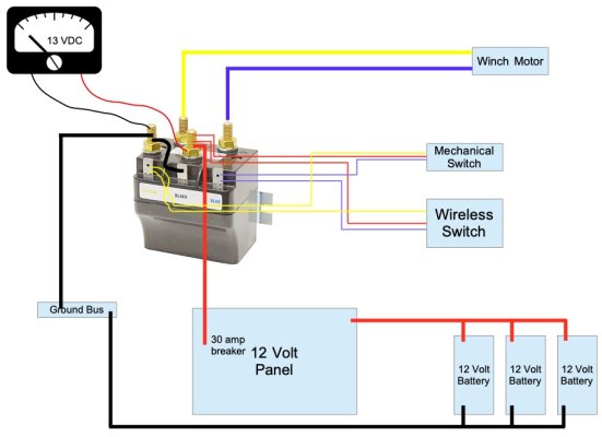
Over the winter I spent the time to route the power supply from the box on the transom in the lazarette through the bilge and into the engine room to access our main DC panel. The +12 VDC red lead connects to a 30 amp breaker in the main DC panel and the black ground lead connects to the main ground bus.

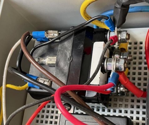
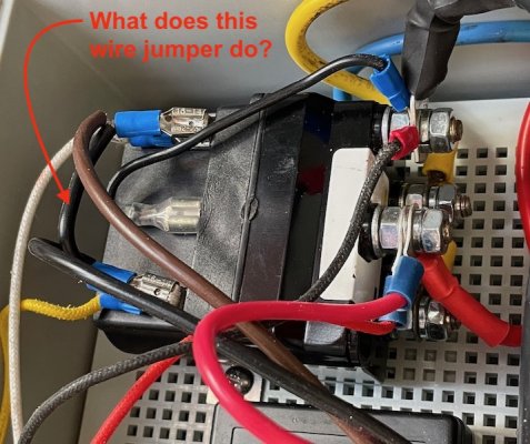
My meter shows 13 VDC at the red and black terminals of the reversing solenoid and the solenoid clicks confidently when either remote switch is actuated, but the winch motor will not turn. Kubota assures me that the motor going out when it sat quietly in a heated warehouse for 6 months is very unlikely.

So why would the winch work when connected directly to a battery, but not when connected to the 12 volt panel when my meter shows 12 VDC at the black and red? What am I missing?
 

Attachments

  • IMG_8355.jpeg
    IMG_8355.jpeg
    142.6 KB · Views: 11
  • Dinghy Butler Electrical Diagram v2.0.jpg
    Dinghy Butler Electrical Diagram v2.0.jpg
    95.4 KB · Views: 20
At the relay blue/yellow terminals, do you see 12 volts. If yes then your connection to the motor wires are not connected. Assumption made that you are using the correct gauge wires.
 
Last edited:
My Fluke T5-1000 shows zero volts across the blue and yellow winch motor terminals whether the solenoid was energized or not. The meter did show +13 VDC between blue or yellow and the black ground terminal when either remote was engaged, depending on which direction was pushed.

The blue and yellow wires supplying power to the winch motor are 8 AWG and approximately 12 feet long. The black and red wires supplying power to the solenoid from the main panel are 6 AWG and approximately 34 feet long.
Ok, when activated the blue/yellow wire to the winch motor is not passing the power through to the motor. I expect connection at relay is crimped wire to terminal, the other end has leads from motor to the extension wires connection point. Look there.
 
Bypass the solenoid and temporarily put the wires directly on the motor and see if it works. If it does you either have a bad solenoid or a bad connection at the solenoid. Our anchor windlass has a solenoid that puts power to the cables going from the stern to the bow. It would click but wouldn’t pass power to the cables. New solenoid and problems fixed.
 
Dave, he already said the solenoid blue/yellow have +13 when activated. The feed wire is not carrying power to motor.
 
The crimps look good, but I appreciate that looks can be deceiving. Some were factory crimped by Dinghy Butler. I will inspect, test, and report back next time I'm at the boat. Thanks Soo.
 

Attachments

  • IMG_9595.jpg
    IMG_9595.jpg
    69.9 KB · Views: 15
  • Dinghy Butler winch.jpg
    Dinghy Butler winch.jpg
    84.1 KB · Views: 16
Bypass the solenoid and temporarily put the wires directly on the motor and see if it works. If it does you either have a bad solenoid or a bad connection at the solenoid. Our anchor windlass has a solenoid that puts power to the cables going from the stern to the bow. It would click but wouldn’t pass power to the cables. New solenoid and problems fixed.

An early misdiagnosis pointed to the solenoid and a new one was provided. I swapped it out over the weekend, but the symptoms did not change. Both solenoids were/are brand new. That said...
 
Just to close this out, the culprit was a jumper between the hot poles of the solenoid contacts that closed both contacts when either in or out was switched on. The result was no power to the motor. Neither the manufacturer nor I can explain why that jumper was in place, but the winch and Dinghy Butler worked just fine when the jumper was cut and then removed.
 

Attachments

  • IMG_9595.jpeg
    IMG_9595.jpeg
    184.8 KB · Views: 9
That looks like a deliberate installation to look like it was needed.
Makes one wonder. 20/20 hindsight, should have questioned that jumper.

On a similar situation a new winch control I installed would not work and in there I found a jumper causing blown fuses. Quality control or sabotage?
 
I think loose engineering is the culprit. The jumper on the original harness (on left) had a connector that could be disconnected. Since I had to extend the circuit, I recreated the harness without that connector (on right). No idea why that connector was in the original jumper and it took me learning about DC reversing solenoids to understand that was the problem.
 

Attachments

  • IMG_9485.jpg
    IMG_9485.jpg
    14.5 KB · Views: 8
Back
Top Bottom