Voltage Sensitive Relay (VSR) Battery Combiner too hot

The friendliest place on the web for anyone who enjoys boating.
If you have answers, please help by responding to the unanswered posts.

chruzz

Newbie
Joined
Oct 24, 2021
Messages
4
Vessel Name
AOZORA
Vessel Make
CLIPPER Hudson Bay 390
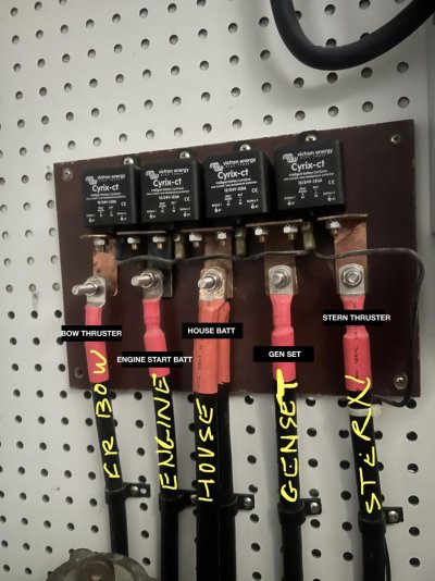
Can anyone have a look at the image and shed light on why the VSR mounting elbow from the engine has gotten so hot that it has become black and melted the board it was mounted to?

I noticed it after my bow thruster battery was dead.

Alternator is 160amp but the VSRs are only 120amp.
Mastervolt Mass Combi Ultra 12/3000 inverter/charger

Attached is wiring diagram of boats 12v.

Lastly, is this VSR mounting setup how other boats are wired?
 

Attachments

  • VSR.jpg
    VSR.jpg
    119.5 KB · Views: 112
  • AF7DDFD0-3BB2-4D0A-A252-72FAC4A1E62E_1_102_a.jpg
    AF7DDFD0-3BB2-4D0A-A252-72FAC4A1E62E_1_102_a.jpg
    84.4 KB · Views: 55
I will give an guess that if your thruster battery went dead. then the ALT might have output 160A to charge it. Causing the copper to heat up and turn black. Again just guessing.

I installed a heat sensor on my ALT just for that reason. If something happened the ALT would back off rather than burn it self out.

In the diagram, I am not seeing any fuses. There must be, but is there any?

Whats funny about the pic is that your cables are black and not red. Plus that setup looks home made. Nothing from a technical point makes this wrong if its sized right. But is it? My point is, why set it up this way. They make buss bars which would be better and the terminals look to small to accept battery cables. What else was done on this level? I would what it to look like a professional install which may be a safer.

If you look at Blue Sea's https://www.bluesea.com/products/7610/SI-ACR_Automatic_Charging_Relay_-_12_24V_DC_120A At 120A the post are 3/8", its hard to tell but those look smaller.

I would have a boat electrician go though your wiring. But that's me.
 
Last edited:
One possibility is corrosion. If you have it where the cables join or the point of impact on the contacts, the reduced conductivity generates heat under heavy amperage.

Ted
 
I'm not familiar with that particular relay but when I was searching & considering alternatives to replace my OEM diode isolators I was concerned that if thruster and /start/house banks were combined when thrusters were activated would the relay handle any hi amp "back flow" to satisfy thruster draw.

Some of the relay mfg advised against using theirs in that situation.
I ended up using a Sterling CVSR and Sterling confirmed it was an ideal choice where hi amp loads might be present.
More info on my Bacchus website- Projects Pg 4 if interested.
 
Churzz.

I would suspect that the nut and washer that secures the bolt to the copper elbow and resides under the cable lug is the problem.

If so, a fix would be to remove the elbow and if you have confirmed that the area of the copper within the elbow exceeds the area of the attached conductor's copper (eg. 75mm^2) remove the existing bolt and polish (320 grit paper is fine) the elbow bright.

Replace the existing bolt with a Copper one (watch out later when tightening up the lug, they are soft), a Silicone Bronze one or even a Brass one. Any of these will do as you are going to carefully Silver Solder the head of the bolt to the back side of the copper elbow, which results in the bolt being captive without any nut required. Now you have a stud.

Clean everything again and if it was me I'd then have them all Tin plated, likely worth about $50 USD and a weeks wait.

Carefully clean the Cyrix-CT's connection pads and the wire lugs using 1000 grit paper as the tin plating is thin (replace the lugs as necessary) and tighten things up appropriately using a nut and washer make from the same material as the bolt/stud. Yes, Tin plate these as well.

What you need to achieve is full contact between the wire's lug and the elbow. The stud and nut are only a clamp and if the clamping force was adequate could be non conductive nylon, but don't go there.

An alternative would be to discard the elbows and replace them with one that are fabricated from say 6mm thick copper that you can drill and tap for the bolts. Lock Tite the bolts in, tin plate the works first and you're good.
 
Another couple of notes I see are:
--I assume the Engine labelled cable also is from the alternator. Correct???

-- there appears to be a washer or nut between the copper sheet and the Engine Cable. That should not be used in a situation like this. The actual cable lug should be bolted straight to the copper elbow with NO washers, no nuts or the like between the copper elbow and the wire termianal as they can add to resistance. If the nut is anything but copper or at least silicon bronze that would add to the problem.

--What is the bolt , nut and any washers made of? Should not be anything like SS. Best would be copper bolts and nuts but silicone bronze or brass would be a huge improvement over SS.

--I guess also that there is no anticorrosion paste such as NoAlox used between the cable terminal and the copper pad. There should be, to me , in cases like this to help stop interface corrosion/oxidation which raises the resistance.
Ideal makes Noalox
Burndy makes Penetrox
Also can use silicone grease often called dielectric.
Don't need gobs of any of them , just a thin,good coat both sides of the cable terminal, which will seal the atmosphere out. Any excess will be squeezed out of the contact areas to be wiped off after the joint is tight.

--To me the Engine labelled copper elbow appears to be borderline adequate and maybe actually not adequate. If less than 1/16" I think on the light side since this is likely the supply line to all the other branches.

-- the generator and the house batt leads are also is darkening. Same comments about copper thickness and any washers or nuts other than the clamping one.

-- all surfaces should be cleaned to bright. Fine sandpaper or Scotchbrite
would be suitable. As you reassemble apply the antioxidant.

--I will suggest that the contact areas between the ACRs and the copper elbows should be gone over also for the same actions.
 
Last edited:
Thanks, I will find some new bolts and do what you described.
 
Churzz.

I would suspect that the nut and washer that secures the bolt to the copper elbow and resides under the cable lug is the problem.

If so, a fix would be to remove the elbow and if you have confirmed that the area of the copper within the elbow exceeds the area of the attached conductor's copper (eg. 75mm^2) remove the existing bolt and polish (320 grit paper is fine) the elbow bright.

Replace the existing bolt with a Copper one (watch out later when tightening up the lug, they are soft), a Silicone Bronze one or even a Brass one. Any of these will do as you are going to carefully Silver Solder the head of the bolt to the back side of the copper elbow, which results in the bolt being captive without any nut required. Now you have a stud.

Clean everything again and if it was me I'd then have them all Tin plated, likely worth about $50 USD and a weeks wait.

Carefully clean the Cyrix-CT's connection pads and the wire lugs using 1000 grit paper as the tin plating is thin (replace the lugs as necessary) and tighten things up appropriately using a nut and washer make from the same material as the bolt/stud. Yes, Tin plate these as well.

What you need to achieve is full contact between the wire's lug and the elbow. The stud and nut are only a clamp and if the clamping force was adequate could be non conductive nylon, but don't go there.

An alternative would be to discard the elbows and replace them with one that are fabricated from say 6mm thick copper that you can drill and tap for the bolts. Lock Tite the bolts in, tin plate the works first and you're good.

Great advice, thank you for taking the time. I will definitely do what you described.
 
I will give an guess that if your thruster battery went dead. then the ALT might have output 160A to charge it. Causing the copper to heat up and turn black. Again just guessing.

I installed a heat sensor on my ALT just for that reason. If something happened the ALT would back off rather than burn it self out.

I think you are correct about the battery being dead, shouldn't the ACR have cut the charge to the battery after the battery gets below a certain voltage?

How do you install a heat sensor on an ALT? I did some Googling but couldn't seem to find anything useful.
 
Although it might just be poor connections that have heated up, I suspect the whole thing is under-sized for the job.


Assuming the relays are all closed, which they will be if the engine is running, the generator is running, or the inverter is charging (from shore power or generator). The Cyrix-Ct is rated for 120A continuous, and 180A cranking for a max of 5 seconds. Your alternator is 160A, so when charging batteries that are below about 80% SOC, the alternator can (should) overload the Cyrix-Ct. Based on where the burning is located, it would seem this is exactly what's happening. Also, I expect both your bow and stern thrusters draw more than 120A, and even more than the momentarily allowed 180A. So any thruster operation likely overloads the Cyrixes. I'd be surprised if your main engine starter doesn't also draw considerable more than 180A.


The Cyrix 230A might be suitable, but you would need to sort out the thruster current draw, and they are typically quite large.
 
I think you are correct about the battery being dead, shouldn't the ACR have cut the charge to the battery after the battery gets below a certain voltage?

How do you install a heat sensor on an ALT? I did some Googling but couldn't seem to find anything useful.


Reading the Cyrix datasheet, as long as one connected battery is receiving a charge (voltage is elevated), it will remain closed. The exception is if the other battery is really stone dead (I think they say 2V), and if that's the case the thruster won't work at all because it's battery is dead, and there is no connected battery to boost it.


Iggy brings up a good point, and there is even more to it that might be at play here.


When all batteries are charged and healthy and the Cyrixes are closed, thruster operation will draw current from all batteries in proportion to their connected resistance. The thruster battery would be expected to contribute the most, but all the other batteries will contribute too with that current flowing through the Cyrixes. As any one battery starts to age, it will contribute less to whatever load is present (thrusters, starters, etc.) and more will have to come from other batteries via the Cyrixes. This will further stress the Cyrixes.
 
It’s unclear to me where the volt sensing is taking place. But the relay won’t de-energize if the supply voltage is above the threshold. The receiving battery isn’t the decider whether or not it gets connected, the supply one is. So a low battery will put a big draw on the entire system.
The whole buss looks a bit undersized to me, as do the relays themselves. I think Victron makes a 250 amp version of that relay which might be a better choice for you. It also looks like some of the relays are getting powered through the output side of one or more of the others. This puts a big strain on the first in line from the alternator.
I’d see what the resting voltage on each bank is, that will help you see what started the issue. If all batteries are ok, it’s probably one pf the issues already mentioned.
 
I don't think your board construction is sound.
Stainless steel is not a great conductor, copper is what to use. Especially where you have a nut (and maybe washer/s between terminal and bus bars.

Your choice of copper flashing material is also too thin for the amperage involved. No doubt the blackened pieces have transmitted excessive heat into components as well.

I would start over for safety reasons.

Absolutely no S/S nuts or washers between the cable and the bus bar. Use copper nuts and washers if you need them there. It is hard to tell from the photo how thick the copper bus bars are, but they do seem rather thin.
 
I have heard the same thing from other sources. Don't use SS nuts or bolts on cables.

So that got me thinking about my VSR and remote switches from Blue Sea.

The nuts and post are SS. So how bad can they be? I just don't know but it makes me think.
 
The nuts and studs just clamp the cable connectors to the copper bus bar. No S/S between the cable connectors and the bus bar. S/S is ok on top of the cable connectors just not in between.
 

Latest posts

Back
Top Bottom