Time to document/update Electrical Systems

The friendliest place on the web for anyone who enjoys boating.
If you have answers, please help by responding to the unanswered posts.

The Brockerts

Senior Member
Joined
Oct 17, 2014
Messages
246
Location
USA
Vessel Name
Moonstruck
Vessel Make
1990 Californian/Carver 48 MY
In my new to me 1990 Californian/Carver MY, I've completed a rebuild of the the waste systems, the bottom, the kitchen and now I'm moving to the electrical systems. Need to document how it's configured first, and I'm looking for idea's on the best way to do that. Very few wire's are labeled on both ends.

Do I just start turning things off and go looking for what doesn't work?, Do I disconnect wire's and run continuity tests on wires?, Combination of both methods?

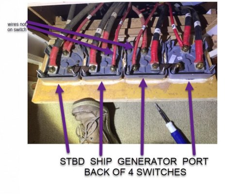
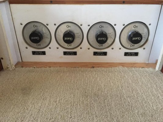
I've attached a few pictures. I have 2 battery banks. Each bank is 2 -8D connected in parallel and it looks like one for port engine and one for starboard engine. I've got 4 simple on/off switches. Look like the generator is connected to the port battery bank and the house is connected to the STBD battery bank. So the house only uses on battery bank?

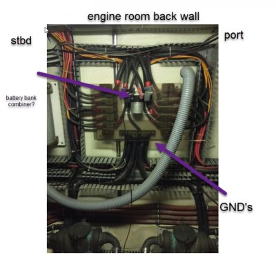
It looks like wires run from the battery + to the 4 switches first and then to the panel in the engine room. Seems reasonable.

However there are 2 wires that do not go thru the switches? I'm guessing something like bilge pumps maybe ?

I'm looking for some words of wisdom from this group before I dig into this project.

The Brockerts
 

Attachments

  • back4switches2.jpg
    back4switches2.jpg
    72.1 KB · Views: 66
  • 4switchesFront.jpg
    4switchesFront.jpg
    146.7 KB · Views: 64
  • backpanel.jpg
    backpanel.jpg
    65.5 KB · Views: 71
I would start by labeling everything you can identify by turning it on and off.

I would guess the unidentified wires in the first picture could be bilge pumps, but my first guess would be a 120 VAC to 12 VDC battery charger. If it is the bilge pumps, I would expect a dedicated panel with switches and breakers or fuses.

In the third picture, that looks like a continuous duty solenoid to combine the banks. Finding the trigger for that solenoid may prove interesting.

A pet peeve of mine is using the word ground on a DC system. There is no ground. It's either positive, negative or it may be part of the bonding system. That looks to be the negative buss.

Ted
 
Last edited:
When you get to mapping the wiring the Elegiant cable tracker is an inexpensive tool for tracing wires without having to probe the insulation. It makes it much easier to sort out unlabeled wiring. Lines need to be deenergized for testing.
 
Thanks, great idea, turn off all AC power, disconnect DC from batteries and "tone" this boat out.
 
I had a pleasant surprise when I opened the panel on our current boat. All wiring had plastic clip on numerical markers at the breakers and terminal blocks which largely followed the wiring diagram. Unfortunately you have to buy the things in bulk if you want to go to that level of detail.
 
Buy Calder’s book first.
 
Bingo, those cables are connected to the battery charger and they are now labeled !
 
For The Brockerts: A suggestion for the actual documentation of the layout. I've used Microsoft VISIO for many years to generate a written record of electrical system layouts. While a bit of a chore to learn, and nothing like a PC board layout tool with an autorouting function, VISIO allows layering of various wire types and sizes to de-clutter the drawing, and can accommodate almost any level of complexity you desire.

And, printing the final result in whatever size and format works for you can enable you to keep not only an electronic copy available, but printed copies of the schematics and layouts aboard as well.

Regards,

Pete

ps-and I believe "telephone toners" and other such circuit tracing tools require any circuit to be "open ended". In other words, it isn't sufficient to simply turn off ship's DC power by turning off the main battery switch(s). Each DC circuit breaker must be opened-circuited by turning them off individually as well.
 
In the third picture, that looks like a continuous duty solenoid to combine the banks. Finding the trigger for that solenoid may prove interesting.
Ted

Working this device down, I'm finding power from both bank in place on the solenoid, and 2 parallel switches. One switch on lower helm and one switch on the upper helm. Neither one seems to work. I'm thinking you should hear a click/clang when they engage the solenoid at the very least.

Interesting that the switches are just some 12ga wire and the trigger on the solenoid looks to be 2/0 almost, so somewhere is another solenoid/trigger

Would you think there would be a breaker/fuse for these switches?

The Brockerts

Did you try the switches with the ignition on? I built a similar setup on my single engine charter boat with a relay and continuous duty solenoid. With the engine running, pressing a momentary switch closed the relay, the relay closed the solenoid, and turning off the ignition deenergized the relay and the solenoid. It would seem logical in your application that you wouldn't want the solenoid closed (consuming power) when the engine(s) weren't running.

Ted
 
Last edited:
I did not try with the ignition on? I'll play some more today, but now I'm wondering if I understand the purpose of the "parallel mode" is? I'm now thinking it is to parallel the batteries if one banks is dead and you can't start the engine connected to that bank. You would then flip the parallel switch and pull power from the other bank to start the engine.

It's not to combine both battery banks for more Ah for the bank in a continues mode say for use with a Inverter.

The Brockerts
 
My guess would be that it gives you the ability to start one engine with a depleted battery by starting the other first and then closing the solenoid. It would also give you the ability to charge both batteries if the alternator on one engine failed.

Ted
 
Yikes, and put in FUSES! That wiring on the back of those 4 switches should have fuses on every small wire that is fed with a larger wire. It’s an electrical fire waiting to happen.

Ken
 
Yikes, and put in FUSES! That wiring on the back of those 4 switches should have fuses on every small wire that is fed with a larger wire. It’s an electrical fire waiting to happen.

Ken

Not so sure you need fuses there. Pretty sure the standards have a maximum length before a fuse is required between the switch and the wire. Also, where the wire goes and what is on the end will determine the need. As an example, some of the wires go to battery chargers. If the run is fairly short and the output of the battery charger is fused, no fuse would be required at the switch.

Ted
 
Yep, so far in the testing I've found fuses on "every small wire that is fed with a larger wire.

The Brockerts
 
Probably a topic for another thread, or review several threads that I've seen on this topic.

The current setup that looks like the factor setup and function.

2 - 8D's for each of the main engines(3208 375hp)

Starboard engine, 2 - 8D's also feed the ships DC panel needs
Port engine, 2 - 8D's and starter for the Generator

So, If you run down the 2 - 8D's on the Starboard side by running lots of 12VDC like an Inverter, you can start the generator and/or Port engine since they are not involved in anything other that starting those engines. Or you can use the parallel switch and get the Starboard engine going.

This certainly is over kill. 2 -8D's for just starting the Port engine and Generator. Also the "house bank" is shared with the Starboard engine and is only 2 - 8D's providing somewhere where around 225Ah at most for the "house bank"

Some simple changes could make this a much better setup

The Brockerts
 
I would agree that two 8D batteries is probably overkill for starting a 3208 in Texas, but probably not in a much colder area like New England or the PNW. 8D batteries make poor house batteries as its extremely rare to find deep cycle ones in your configuration. That said, many manufacturers visualize a boat like yours running the generator when away from the dock or when you shut the engines off. Depending on your planned use, it should be pretty easy to do a little reconfiguring and end up with a deep cycle house bank to fit your needs.

Ted
 
A 445hp Chevy Duramax starts instantly with two Group 78 batteries. At 15 degrees below zero it will start in one to two seconds. So, I just don't get the need for a monster, dedicated 8D starting battery.
Probably a topic for another thread, or review several threads that I've seen on this topic.

The current setup that looks like the factor setup and function.

2 - 8D's for each of the main engines(3208 375hp)

Starboard engine, 2 - 8D's also feed the ships DC panel needs
Port engine, 2 - 8D's and starter for the Generator

So, If you run down the 2 - 8D's on the Starboard side by running lots of 12VDC like an Inverter, you can start the generator and/or Port engine since they are not involved in anything other that starting those engines. Or you can use the parallel switch and get the Starboard engine going.

This certainly is over kill. 2 -8D's for just starting the Port engine and Generator. Also the "house bank" is shared with the Starboard engine and is only 2 - 8D's providing somewhere where around 225Ah at most for the "house bank"

Some simple changes could make this a much better setup

The Brockerts
 
A 445hp Chevy Duramax starts instantly with two Group 78 batteries. At 15 degrees below zero it will start in one to two seconds. So, I just don't get the need for a monster, dedicated 8D starting battery.

A bunch of that has to do with a modern gear reduction starter versus 50+ year old technology in a 3208 or for that matter 6-71 starter.

Ted
 
Have you tried asking Carver if they have any documentation from the original build?

I'm not familiar with the brand so maybe it's known that they don't have anything available, but if it's available it will save you a whole lot of time. I was able to get a full wiring diagram for my 1977 Uniflite from a company that bought out all of Uniflite's documentation, parts and rights so 95% of the original wiring still present is no longer a mystery.
 
I actually have the schematics shipped with the boat. I pulled them out and worked with them to install the inverter. However I stopped using them after finding about the 10th error. Even the original numbers on the cables didn't match up. I had cable marked 412 on one end an 87 on the other end. My panel breaker says "water heater", that cable goes to the aft receptacles and it looks like factor install, not something someone installed. I use them as a base before tracing a wire but finding to many issues. I think the problem is that this boat is a 1990 Californian built by Carver. During purchase I went thru 6 of these 1990 Californian/Carver boats all over the US with a manufacturing range of about 8 months and it was amazing how different somethings were. They all had the exact same layout and lots of crazy things, like a hatch cover that was 6 inches to the left and therefore would not allow access to the sensor in the holding tank. I'm losing the "trust but verify" feeling, now it's just "look and trace"

The Brockerts
 
Tracing 12v Wires

When tracking down wires, I have often used a small but very loud 12v siren. I hook it up to one end of the wire and to a good ground. When I energize the other end of the wire the siren goes off. I have tested wires from the weather helm to the flybridge and to the stern. I really like my test siren, but sometimes neighbors come running to see if the boat is in distress. ?
 
In the past the 8D was the work horse for the 18 wheelers and coach folks.

They are usually built as compromise batts . Not as many plates as a true start batt , but with room inside the case for chunks to drop from the plates.

The OTR folks would leave bunches of lights on all night while parked , and still need to start in the AM.

SO there not as good as true deep cycle batts for house use , but if not regularly run down very deep, they work fine.

3-4 years was considered acceptable life , and most did fine as the days run could bring the batts back to 100%


GOD! They are heavy , but at 160-180 lbs be sure any the replacements weigh a similar amount.
 
Last edited:

Latest posts

Back
Top Bottom