shunt with 4 posts

The friendliest place on the web for anyone who enjoys boating.
If you have answers, please help by responding to the unanswered posts.

LeoKa

Guru
Joined
Apr 15, 2017
Messages
1,150
Location
USA
Vessel Name
Ironsides
Vessel Make
54' Bruce Roberts steel sailboat hull, coastal LRC, 220HP CAT 3306.
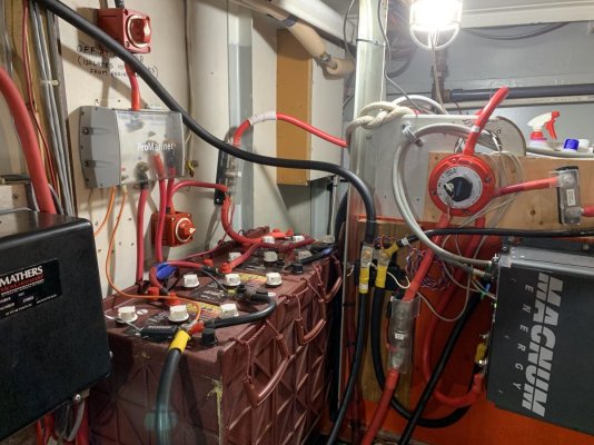
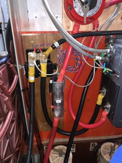
My battery monitor has died (or not) and I bought a new one. Unfortunately, it does not come alive. I took pictures of the original cable configuration, but I cannot reinstate that, because the shunt, which comes with the monitor has only 2 posts. The original cabling on a shunt with 4 posts.

I have been searching for a shunt like that (500A/50mV) but I cannot find the same setup. See photo.

I have 2 banks, 4 Trojans in each, 12V series/parallel wiring. The inverter charger is Magnum as well (3112) Modified Sine. Nothing has really changed, I just cannot connect all the wires on the 2 posts shunt as it was before.

Anyone knows a place, where this type of shunt with 4 posts can be purchased?

Thanks. IMG_0930.jpgIMG_2250.jpg
 
Last edited:
The purpose of the double shunt was to monitor two battery banks. It is two shunts tied together at one end.

You can do the same thing with two separate shunts by installing a jumper between the two terminals going to the battery negative terminal. Or running separate cables from each shunt to the battery negative terminal.

Xantrex may still carry those.
 
The purpose of the double shunt was to monitor two battery banks. It is two shunts tied together at one end.


I tried to figure this out over the weekend. No success.

- first, I put back the double shunt and mimicked the original wire configuration with the new battery monitor. No LED. Voltage of 13.47 on contacts #3 and #4.

- second, I did the same with the new shunt (single) for both battery banks. No LED.

- third, I put only one bank onto the new shunt (single), following exactly what the manual says for configuration. No LED and the required voltage is present on #3/#4.

I cannot imagine that an LED is dead on both sensors. I don't think the brand new sensor is bad out of the box.

What other troubleshooting could you recommend?IMG_0939.jpgIMG_0940.jpg
 

Attachments

  • jUQ4wwfKSNeB7tN3tC65uw.jpg
    jUQ4wwfKSNeB7tN3tC65uw.jpg
    158.6 KB · Views: 46
Last edited:
When you say no led, does that mean the led is not lit or it reads 0?

The wires from the shunt provides signals for the meter but the meter has to have it's own power source.

And which battery monitor are you using? Bf
 
Victron Energy Shunt 1000A/50mV-0, 5 / 2xM10


Ouch, over a 100 bucks?
I guess, if you have 2-4 banks, it is worth it. Lot of copper.
Thanks.
 
When you say no led, does that mean the led is not lit or it reads 0?

The wires from the shunt provides signals for the meter but the meter has to have it's own power source.

And which battery monitor are you using? Bf

Magnum Battery Monitor. You can see it on the photos. I think they only sell one kind.
Yes, the monitor gets its own power with a separate wire, including a 2A fuse in between. The troubleshooting guide's first step is to check the voltage for the monitor. The voltage is accurate and the current goes into the monitor housing. This is the only step the guide recommends to check, if the LED on the monitor is not lid up. They say, there is no power in that case. Well, the wire going in has power and the monitor is brand new.
I could check the LED connections, but I don't have a schema and I don't know what voltage an LED gets on a board.
I doubt that the shunt has anything to do with the LED. Plus, the unit is very easy to setup. The guide is clear and looks simple to connect things.

Unfortunately, my Remote Control Unit has a bad screen, so I cannot tell for sure, if the battery monitor is sending data there. Once I fix the LCD on the RC, I will be able to tell the readings. I can see the voltage and amp on the RC LCD, but nothing else, because the display is half gone.
What I am trying to say is that the battery monitor might be working fine and sending data to the RC, even if the LED is not on. I cannot answer this question now. The LCD has to be fixed first on the RC.
 
It appears that the Magnum BMK sense module that you have is only designed monitor a single bank and your boat has at least two banks.

https://www.magnum-dimensions.com/file/2224/download?token=52U1pe--

It also looks like your shunts are incorrectly wired. One side of each shunt should be connected ONLY to it’s bank battery negative terminal. The other side should be connected the the negative load bus. One of the shunts in your pictures looks like one stud is broken or cut off. (?!)

I don’t think the bonding wire should be connected as shown, but if it is then it should be on the load side of the shunt - not the side where the battery is connected.

Suggest you find a marine electrician to go over the system for safety sakes

The sense module blue and red pair should be connected accordingly to either side of the shunt for ONE battery bank that it is monitoring. Ask Magnum if their system can use a second sense module to monitor a second bank.

If you are not getting any LED on the module check that it is getting power on terminals 3&4 of the connector block, and check that the connector block is seated properly in the sense module per the manual.
 
It appears that the Magnum BMK sense module that you have is only designed monitor a single bank and your boat has at least two banks.


https://www.magnum-dimensions.com/file/2224/download?token=52U1pe--


It also looks like your shunts are incorrectly wired. One side of each shunt should be connected ONLY to it’s bank battery negative terminal. The other side should be connected the the negative load bus. One of the shunts in your pictures looks like one stud is broken or cut off. (?!)


I don’t think the bonding wire should be connected as shown, but if it is then it should be on the load side of the shunt - not the side where the battery is connected.


Suggest you find a marine electrician to go over the system for safety sakes


The sense module blue and red pair should be connected accordingly to either side of the shunt for ONE battery bank that it is monitoring. Ask Magnum if their system can use a second sense module to monitor a second bank.


If you are not getting any LED on the module check that it is getting power on terminals 3&4 of the connector block, and check that the connector block is seated properly in the sense module per the manual.


Yes, I did check the power on those terminals and there is power going in to the sense unit.


At this point, the old shunt is removed and only the single shunt is installed, with only one battery bank connected.


Still no LED on.


The old shunt with 3 posts was originally installed by a boatyard's electrician, so it was properly done. It is short of one post, so you are correct. It should be 4 posts there, originally.


The sense unit was working fine, before the water damage, which killed my inverter/charger and the battery monitor. The wiring you see on the first photos was the original setup, prior to the damage. Later, I just simply replicated the same configuration with a brand new battery monitor I have purchased. (there is a new Magnum inverter/charger installed, as well)


The present wiring is exactly as it is in the ME-BMK manual, with only Bank 1 is connected to the battery side.

View attachment 91336IMG_0958.jpg
 

Attachments

  • IMG_0956.jpg
    IMG_0956.jpg
    147.6 KB · Views: 30
Last edited:
I have a similar configuration, my old Freedom 30 had the Link 2000 monitor that tracked 2 banks. The new Magnum only tracks 1 bank, but it was simpler to keep the old shunt in place and simply wire it to monitor only a single bank. Not an issue. The other posts then became a buss post. Make sure your power supply to the BMK module is fused and it's getting 12V. Insure the polarity on the blue/orange pair is correct, good contact, and that they are twisted. If you're not making progress, call Magnum Tech support. They know more about it than anyone you'll get a response from on the forum, me included! They're only a phone call away, I've found them to be helpful.
 
I have a similar configuration
included! They're only a phone call away, I've found them to be helpful.


Yes, there is proper voltage on #3/4 connections. The fuse is in place and tested. The twisted wire is connected according to the manual. The new single shunt is mounted. Only a single bank connected now. (see photos)

I did call Magnum, but after 35 minutes on hold, I hung up. I will try it again.
 
From the docs if you confirmed that power is applied on the sense module and there is no LED then the sense module is probably defective. But I would still confirm a) it's got power on the #3/4 terminals with a voltmeter and polarity is correct, and b) the terminal block is seated properly in the module. Those type of terminal blocks can easily be partially pushed in resulting in no connection.
 
From the docs if you confirmed that power is applied on the sense module and there is no LED then the sense module is probably defective. But I would still confirm a) it's got power on the #3/4 terminals with a voltmeter and polarity is correct, and b) the terminal block is seated properly in the module. Those type of terminal blocks can easily be partially pushed in resulting in no connection.


I called Magnum and the problem is fixed. It was the wiring on the wire block. It was wired backwards. Position #1 was on #4, etc.
I have not changed the wiring. I just connected the block to the sense unit out of the box. The block itself has no numbering, so it is not easy to tell, if the wires are connected in the right order. The voltage was there on wire 3/4, but they were not in the right place on the block.
The LED is alive!

Thanks guys.
 
Back
Top Bottom