Right way to split wires?

The friendliest place on the web for anyone who enjoys boating.
If you have answers, please help by responding to the unanswered posts.
I'm with Dave on this one... why bother with 120V lighting?

Just to clarify, I'm in Russia so any AC will be 220v. I don't think it changes anything in this context, though.

Already spoke to why I am stuck with this AC lighting problem :)
 
Just to clarify, I'm in Russia so any AC will be 220v. I don't think it changes anything in this context, though.

Already spoke to why I am stuck with this AC lighting problem :)


If they are LED lights, and several fixtures run off one small power pack...chances are the lights are actually DC.


That is why I suggested you may be able to use a different power source from DC power instead of AC.
 
If they are LED lights, and several fixtures run off one small power pack...chances are the lights are actually DC.


That is why I suggested you may be able to use a different power source from DC power instead of AC.

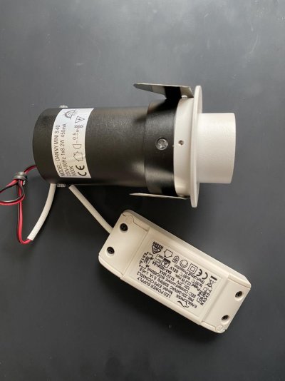
Unfortunately, each fixture is individual and has an integrated power supply.

They are quite spendy or I would just replace them with something natively DC. I thought that since I am running AC (in a separate conduit, thanks!) for outlets it wouldn't be a big deal to have these lights wired as well.

Once I started to plan the wiring, I realized that where boats are concerned, I don't know the right way to splice wires.
 
I wish other electricians would check me on this. The ABYC guy I used recommended larger gauge wires for long 12-V runs to terminal blocks or fuse blocks to prevent voltage drops. From there, each appropriately sized wire is fused—either on the fuse block or, if using a terminal block, via an in-line fuse—to the load. OR, in one case, the fuse protecting the entire circuit is sized to protect the smallest line in the circuit. Not arguing that light circuits should be wired this way (mine aren’t). If the OP wants to wire for lights only (and I recognize that was the original question) the schematic Kevin and others are recommending is fine. But if he thinks he’ll have additional DC loads in the same area some distance from his house bank in the future, there are other ways of doing that.
 
I wish other electricians would check me on this. The ABYC guy I used recommended larger gauge wires for long 12-V runs to terminal blocks or fuse blocks to prevent voltage drops. From there, each appropriately sized wire is fused—either on the fuse block or, if using a terminal block, via an in-line fuse—to the load. OR, in one case, the fuse protecting the entire circuit is sized to protect the smallest line in the circuit. Not arguing that light circuits should be wired this way (mine aren’t). If the OP wants to wire for lights only (and I recognize that was the original question) the schematic Kevin and others are recommending is fine. But if he thinks he’ll have additional DC loads in the same area some distance from his house bank in the future, there are other ways of doing that.

Your idea of inline fuses works just fine. The idea is that you should not have as an example a 50a fuse protecting 6AWG wire to a terminal block that splits this to several 12AWG wires.

The idea of distributed fuse panels is a great idea, but my take was from the OP's original post (and perhaps I missed something) was that he was trying to figure out the way to wire a single lighting circuit with multiple lights.

:thumb:
 
Greetings,
Mr. ATG. Give your girl a big wet kiss then install her LED lights in your house somewhere or sell them on S-Bay (I'm guessing the Russians have an equivalent to E-Bay.) Buy the appropriate lights and give her another kiss. Don't complicate matters when you don't have to.
After all, this IS a learning experience for you both.

KISS. Keep it simple, sailor.
 
No hidden splices or terminal blocks. All connections must be accessible. There is no need for AC and DC lights any more. DC only lights. AC receptacles. Pick up a Nigel Calder book.

Good advice.


What some are suggesting here regarding terminal blocks might sound interesting but is is frankly not necessary or practical on many or most boats. It is also just not how things are generally wired by professionals.

A lighting circuit, starting at a overcurrent protective device is wired 100% in series from device to device with the connections to those devices being parallel connections to neutral for AC or ground for DC circuits.

This methodology is demonstrated time and time again in pretty much every thing that has lighting or outlets.

Why??? simple, it's easy to install, its inexpensive, its easy to work on, and it works.

A single circuit also MUST have ALL wires downstream of the overcurrent protective device rated for the full current rating of that device. You CANNOT run a larger wire to a terminal block and then smaller wires out from there.

Some here are giving out advice on subjects that they are frankly unqualified to give advice on, based on the fact that the advice given, if followed, creates a unsafe installation risking a fire, injury, or even death.

The CB used is to protect the smallest wire used in the circuit. The minimum wire used must be sized for the ampacity of the device/load used. If you run a #12 wire to a TB to avoid excessive voltage drop, and connect 4 #16 wires for lights on the TB and use a 15amp CB you are safe and 100% legal. In many cases it is not easy to get to an overhead light to "daisy chain" or wire in series all the lights but much easier to run the light circuits to a central location for connection on TB's. In modern DC LED lighting it is very permissible to wire 10 LED lights using 10 individual #16 wires to a 10 terminal TB with all 10 termination points jumpered to a #12 supply wire and use a 15 amp CB. If any 1 circuit has wire sized smaller then the example of a #16 the CB would have to be reduced in size to that wire size, such as a #18 having the CB downsized to 10 amps.
In this way it is easy to remove a bad device from a TB that is causing the CB to trip.

Having graduated with a EE degree in 1971, spent 22 years in Industrial Control in open pit coal mining (120v - 69KV circuitry), 15 years in Industrial Control in manufacturing (120v - 4160v) and 6 years in marine electrical and electronics (12v -120v) I would consider myself in some way a "professional". I do although readily admit I know the NEC far better then ABYC standards.
 
Last edited:
Greetings,
Mr. ATG. Give your girl a big wet kiss then install her LED lights in your house somewhere or sell them on S-Bay (I'm guessing the Russians have an equivalent to E-Bay.) Buy the appropriate lights and give her another kiss. Don't complicate matters when you don't have to.
After all, this IS a learning experience for you both.

KISS. Keep it simple, sailor.

This is the right plan. However, the lights have arrived and it seems that they can be wired directly to 24v DC based on this power supply...??
 

Attachments

  • LED.jpg
    LED.jpg
    82.3 KB · Views: 20
Last edited:
In the schematic, what is the blue control wire?

I would also like to know the answer to this. In addition, where there is a "T" in the schematic...what is happening there? Can someone show me a pic of what that looks like with actual wires? This was actually my original question :)
 
I would also like to know the answer to this. In addition, where there is a "T" in the schematic...what is happening there? Can someone show me a pic of what that looks like with actual wires? This was actually my original question :)
There are a few ways to do this.
One I have used successfully is a reducing or step down butt crimp connector. The large end would contain 2 wires and the small end a single thus forming a Y or T in the wiring. Here is one example...uninsulated shown for clarity.
There are many sizes & styles of these available both insulated and uninsulated (where shrink wrap is used to then insulate) Best to use a quality crimping tool for best performance.

https://www.delcity.net/store/Non-I...7HWuiKcAsB0rN6xgsS9y5furBbpkGg-RoC4noQAvD_BwE

From that link click on X and Y connectors to see another way to connect 3 or 4 wires. Note these will need to be insulated at the center if not connected to a screw.

There are also multi wire crimps where the 3 (or more) wires are simply captured in one crimp.
https://www.delcity.net/store/Multi!Wire-Closed-End-Connectors/p_823991.h_823992
 
Last edited:
@Bacchus,

Thanks! This is very helpful!
 
Greetings,
Mr. B. While I appreciate the use of multiple wires being connected via a single termination, I've found that such a practice does make it difficult to trace single wire/ point faults. IF I have the room, I use individual end terminations and stack them on a terminal block. I am by NO means an electrician!

I don't disagree but think the OP was mostly concerned with how to create a Y split in wires to serve another fixture. I was assuming fixtures had pigtails vs a screwed terminal.
I did mention screwing the center of a Y or X connector and agree in that situation may be better with individual ring terminals.
 

Latest posts

Back
Top Bottom