New batteries setup

The friendliest place on the web for anyone who enjoys boating.
If you have answers, please help by responding to the unanswered posts.
Check with your local marine store, all ours stores around here have them and allow you to borrow them.......:thumb:

Last summer, while in Mike's marina in Sidney, I had to replace the wiring to my windlass. I had three of the ends crimped at the store, but they all had to pass through the deck, and I didn't want to have three holes any larger than the wire size, so the last three crimps had to be done in place. I found that the local marine store was happy to loan the tool, since I was spending my $ there. Made the job much easier.
 
Breakers are much pricier, and relatively complex compared to fuses, for safety gear I prefer KISS.

Lots of crappy stuff sold online too, but Blue Sea is trustworthy, as long as you know what you're doing.

If you do go CB, make sure the delay rating is very short.
 
Last question (well maybe not the last) about cables as I am not very familiar with cable of that size.
I know bigger is better but there is also a price tag so the question is would awg 2 be fine for this setup? I look at amp table and looks like it should be, from ancor it is given for 178amp in er and 210amp outside er. My longest run would be something like 4 to 6 feet max to the main panel, and less than that between alt, charger etc

Or should I go to 1/0?

L
 
Get to know the Circuit Wizard app from Blue Sea.

Ask Qs here while learning.

Double distance for round trip.

Some applications 3% voltage drop is too much!
 
Get to know the Circuit Wizard app from Blue Sea.

Ask Qs here while learning.

Double distance for round trip.

Some applications 3% voltage drop is too much!


I grabbed this pdf a few years ago and have used it extensively ever since. I keep a copy in my dropbox so I always have access to it.
https://www.bluesea.com/products/20010/Wire_Fuse_and_Fuse_Holder_Selection_Chart


Looking at it, with that amperage and the distance (round trip as John mentioned) you would want 2/0 to stay withing the 3% voltage drop.
 
"Or should I go to 1/0?"


Never have I heard ," gee I wish I used thinner wire".
 
Never have I heard ," gee I wish I used thinner wire".


Well... I have said it. :) on our old boat I used 4/0 wire for the DC refit and it was pretty awkward to use in tight spaces and especially for the jumpers between battery posts. The lugs are large and you can’t put more than one of the “good” ones on a golfcart battery post. On the current boat I did the same refit and kept it to 2/0. It was much easier the manage. Sure, there is a capacity thing, but I am happy to minimize the risk by never trying to max out the DC loads and protect the wire with proper fusing.

1/0 is kind of an “odd” size. There is a lot more standardization and availability at the 2/0. If you need to replace something, most marine stores jump from 0/0 to 2/0 then to 4/0. So the old, “Dang, I need just one more lug and one more foot of wire” trip to West Marine may have you compromising on wire size and lugs... or worse... having to place a special order. But this isn’t an absolute. It is just what I observed. YMMV
 
Serie Parallel battery wiring

I am at the point of wiring my new battery bank (4 GC2 6V).
Here are 3 way of parallel serie wiring. Any advice on which one should be the best, if there is any real difference between the 3 etc?
Just want to avoid useless cable length.

Version 1:
Serie%2FParalell connections (1).png

Version 2:
Serie%2FParalell connections.png

Version 3 (matching the Calder book recommendation)
Serie%2FParalell connections (3).png

L
 
Correct me if I am wrong, but #1 won’t work at all. And I am having trouble wrapping my head around #3. So #2 would be my reco.
 
Correct me if I am wrong, but #1 won’t work at all. And I am having trouble wrapping my head around #3. So #2 would be my reco.

#1 is two pair of 6v in series (so 12 v) connected in parallel (2x220Ah)
#2 is two pair of 6v in parallel (2x220Ah) connected in series (12v)
#3 is same as #2 but with cross links as recommended in Calder book.

Amp and volt wise these 3 should be equivalent, only difference is cable length. So my question about the best option knowing that shorter the cables less the expense (and cable management mess). I want to avoid falling in a trap of charge/discharge imbalance among the 4 batteries of the bank.

L
 
You need to make 2 sets of 12 volt batteries by jumping from positive on one battery to the negative on another battery. Do this 2 times with 2 sets of your batteries. You now have the series part done. Now you want to put your 2 new 12 volt batteries in parallel by hooking the two positive battery posts together and the two negative posts together. On each new 12 volt battery you should have a jumper from one positive post to the negative post on the other 6 volt battery. When I say the positive posts I mean in the 12 batteries you made up go to the positive post that is empty. Same with the negative posts that are empty. I drew a quick diagram, not as pretty as yours... This way you will use both sets of 12 volt batteries by going off the positive post of one 12 battery and off the negative post of the other 12 volt battery.
 

Attachments

  • 4774713F-08C8-4A82-8F92-07CD1773A033.jpg
    4774713F-08C8-4A82-8F92-07CD1773A033.jpg
    105.6 KB · Views: 57
One and two will send 6v to the panel. Three will work but I second comdave’s drawing.


I'm an idiot so pay no attention to me.
In both drawing #1 and #2 you will get 12v to the panel.


In #1, the 1st two batteries on the left are connected in series to create a 12v bank. The same is true of the two batteries on the right. Those two banks are connected in parallel to give a large 12v bank.


In #2, the first two batteries are connected in parallel giving a larger 6v bank. The same is true for the two batteries on the right. These two 6v banks are then connected in series to give a bank of 12v.


I think either would work, but I would take the pos and neg leads to the panel from opposite ends of the final larger 12v bank.


#1 is the same as Dave's drawing other than Dave has the leads coming off the ends of the bank properly.


Of course, I'm often wrong....


Edit: OK, I think I am wrong. #1 shouldn't have the parallel and series connections coming off the same post. I still think #2 is fine but I like #3 better.
 
Last edited:
4 - 6 volt batteries to make a 12 volt system

Lou Tribal,


COMODAVE has it right. -- :thumb:
stick with that as a best practice series - parallel wiring design. :)

Stay Away from Version # 1. -- not recommended ! :eek: First - the Com Bus pick up is wrong. Next it looks to me at first blush that only the two center batteries are in parallel, with a 6 volt in series at each end output, - there is a potential to end up with 18 volts depending where you com bus hooks in !
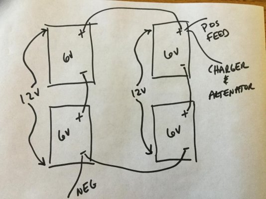
Version # 2 will work if you move the common buss to the other set of batteries to the left & use those negative terminals. Series parallel part is ok - but the pick up points are wrong.

Version # 3 series parallel will work just fine. But it has two longer then needed & parallel interconnections that are redundant, so maybe that is to spread the load for less resistance for use with a thruster or something as Calder does know what he is talking about.
It will work, but has two extra & longer then needed cables that are not needed for most applications. Take the two longer ones out & put in one shorter + to - series wire & your all set.
You said you did not want extra cables !

COMODAVE has it 100% correct. Go with that & you can't go wrong.:thumb:

Don't try to be to fancy as then it will be harder to diagnose if there is an issue in the future.:banghead:

and remember, on boats there is always going to be an issue in the future.:eek:

Good Luck.

Alfa Mike :thumb:


PC: what DHAYS has now drawn below is also good.
 
Last edited:
Two batteries in series and both pair in parallel so this should give a 12v bank of 2x the Ah of each battery. However my question stands about imbalance in charge/discharge.
I tend to agree about Comodave schema, in fact it was what I was planning to do before over thinking the whole as usually :)
But I am interested to learn more about the subject.

L
This shouldn't have an inbalance as the positive and negative are drawn from separate 12v banks.
 
Drawing 51 & 47 are the same. The batteries are rotated 90 degrees but the wiring is the same.

Post 43 version 1. Battery charger will do nothing as there is no connected path. Panel will only see the one 6 volt battery.

Post 43 version 2. Battery charger will charge all batteries correctly however the panel will only see one 6 colt battery.

Post 43 version 3. Everything will work. The charging will be out of balance, should be moved to the same post as panel.
 
As I had some time waiting to resolve my water ingress in oil problem, I finalize what I foresee as my 12v setup. So here is the schematic of what I plan to do:

Bleuvet - 12V Circuit - Revised.jpg

Feedback/comments/laugh are welcome!

Note: I know it is better to have only one bigger house bank but the current 12V batteries I have at this time are still working pretty fine and can provide some extra capacity so I do not want to ditch them at this point.

L
 
Why not combine all three 12v batteries to be a bigger start banks that doubles as a secondary backup bank?
 
Why not combine all three 12v batteries to be a bigger start banks that doubles as a secondary backup bank?

The 3 12V are not of the same type. The two at the top are group 31 deep cycle (my current house bank), the green at the bottom is my start battery (group 64 if I remember correctly).

L
 
The 3 12V are not of the same type. The two at the top are group 31 deep cycle (my current house bank), the green at the bottom is my start battery (group 64 if I remember correctly).

L


In regards to charging charging, that wouldn't matter if they are all lead-acid. :) Then use only a single output of your charger and and ACR between them. (Simpler is always better)

Still, that 64 versus three 31s? Take the three 31s and call it done. That will start any motor your avatar boat will have in it and make a very good back house bank. IMHO :blush:
 
I don't understand this stuff terribly well, but on first blush it seems OK as long as your two house banks are of similar battery types.


OTOH, you can often find decent 6v wet cell GC batteries for under $100 each. With the core refund on the 12v, you may be able to go with a house bank of 8 6v batteries that will give you a LOT more capacity and simplify your setup.


I certainly understand not wanting to trash perfectly good 12v batteries but give it some thought.
As you mentioned I just don't want to trash these batteries,not for the price but just not to trash something for nothing as simplistic as it can seem.
The goal here is to exhaust the 12v and then replace them by 2 or 4 other 6v.
The depicted setup considering my estimated load per day (pessimistic estimate) will allow me to stay almost 3days at anchor with a 50% discharge what will be just perfect for my actual usage.

L
 
I am not criticizing your drawing. I am assuming you have simplified it. The parts that worry me are the splitter and the bow thruster. I would need to know exactly what you are calling a splitter. Bow thrusters use a lot of amps and must be wired appropriately but I am sure you already know that.
 
All the batts in a bank should ideally be identical including mfg date.

Don't plan to add newer to old later on.
 
I am not criticizing your drawing. I am assuming you have simplified it. The parts that worry me are the splitter and the bow thruster. I would need to know exactly what you are calling a splitter. Bow thrusters use a lot of amps and must be wired appropriately but I am sure you already know that.
Don't worry and please criticize!
What I call s splitter is a diode based isolator/splitter that is already aboard. I know t s far from ideal due to voltage drop but after thinking about my actual usage it will be fine for now. Let me explain, we usually are leaving the dock, so batteries full charged, to anchor during 2 to 3 days, then go back to the dock. So mainly it will be the battery charger that will take care of battery ideal charge, more than the alt.
For the bow thruster, indeed it requires heavy cables, I plan to use same cables as for the batteries so 1/0 cables.

L
 
All the batts in a bank should ideally be identical including mfg date.

Don't plan to add newer to old later on.
That is why I made these as 2 separate banks (separate charge, separate discharge). :)

L
 
Back
Top Bottom