More solar questions....

The friendliest place on the web for anyone who enjoys boating.
If you have answers, please help by responding to the unanswered posts.
Dave, for cooling effect you only need 1", but maybe you want to be able to clean underneath.
 
Dave, for cooling effect you only need 1", but maybe you want to be able to clean underneath.

Yeah, I would like to be able to clean underneath. LG says to keep a minimum 4" clearance underneath. That is more than needed BUT if I get at least 3.5", I can move the panel forward so it actually clears my air horns on the PH roof. This will move it further away from shadows from the flybridge.

So, if I can get enough clearance I can clean, reduce shadows, approach the recommended clearance, and avoid the hassle of moving air horns and creating a whole host of other problems.

Dave

......the other advantage is that you may then be able to get your though-deck connections underneath the panels - out of sight, direct rain, and UV.
 
Last edited:
......the other advantage is that you may then be able to get your though-deck connections underneath the panels - out of sight, direct rain, and UV.


That was an other thought as well.
 
Today I took a piece of cardboard, cut the size of the 60 cell solar panel and out it up on the roof of the PH to check fit. It will work. Unfortunately, I will need to clear my air horns. This should be a problem with the mounting I want to use. The edge of the panel will cover the after few inches of the horns. There will be a bit over an inch clearance between the top of the horn and the bottom of the panel.

I also got the quotes back from Platt Electric today. The quote they gave me is about $30 less than their website listed price for the panels.

So I have some more questions....

The cost difference between the 350W panel and the 365W panel is about $60. For those of you running 1 or 2 panels, how much practical difference would that 15W actually make?

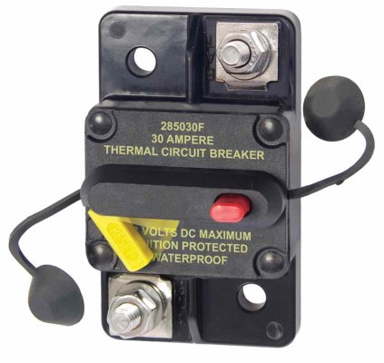
Any suggestions on circuit breakers to use between the the controller and the battery? Since the controller will max out at 30 amps, I was thinking of using something like this between the controller and the battery connection.

IMG_0353.jpg

I also am not sure what size fuse to use between the panel and the controller. The panel will max out at 42.8v at 9.9 amps. Will a 10amp inline fuse be adequate? The wire from the panel connections to the controller will be 10awg.
 
David: that’s the same version Blue Seas breaker I used, but I can’t recall the amperage. I’ll have to check the size of the fuses I put on the Din rail in the box between the panels and the controller, Your supplier should be able to provide advice on all of that.
 
Any suggestions on circuit breakers to use between the the controller and the battery? Since the controller will max out at 30 amps, I was thinking of using something like this between the controller and the battery connection.

View attachment 74201

I also am not sure what size fuse to use between the panel and the controller. The panel will max out at 42.8v at 9.9 amps. Will a 10amp inline fuse be adequate? The wire from the panel connections to the controller will be 10awg.

Anything in-line with the panel wiring equals resistance. Resistance equals reduced power.

I would pay CLOSE attention to any breaker and/or connector arrangement's "ON" resistance and choose the one with the minimum that satisfies all other safety requirements.
 
This is a very common misconception about solar panel installations: There is no need for a fuse/breaker from the panel to the controller. The solar panel has an absolute maximum current producing capability, the Isc spec. Your wiring should sized so it can carry that much current forever. Remember fuses/breakers protect wire not the device connected. Also the controller will prevent any current coming from the battery back to the panels if there is a fault.

And on the other end, I thought you were going to feed the DC system through the DC panel, either through a sub breaker or through the main panel breaker. Your wire should be big enough for even the main breaker (often 50-60 amps). But maybe if you are feeding the main breaker, you want a disconnect and that 30A should work fine.

David


Weeell..........maybe! It depends on the assembled panel voltages. For example, I have four (290W) panels each with a 32vmp. I have them connected in series/parallel, that is two panels in parallel in series with another two panels in parallel. So the voltage arriving at the controller is 64V and can get to be as high as 70V.

I agree with you as to currents but there are other considerations that can necessitate a means to isolate the panels from the controller.

Those are hazardous voltages AND SHOULD BE CAREFULLY HANDLED. I use a battery on/off switch for mine. One should exercise caution working with higher voltage panels along with panels of any voltage in series. JMHO
 
Last edited:
Foggysail:

You are correct about the need for a disconnect with higher voltage systems. At what voltage does the code switch to AC wiring practices rather than the more lenient DC practices. I think it is more than 48 volts, so your installation may get you into the realm of AC wiring.

David
 
Anything in-line with the panel wiring equals resistance. Resistance equals reduced power.


I would pay CLOSE attention to any breaker and/or connector arrangement's "ON" resistance and choose the one with the minimum that satisfies all other safety requirements.


Good point. There is a certain amount of loss even from connections.


This is a very common misconception about solar panel installations: There is no need for a fuse/breaker from the panel to the controller. The solar panel has an absolute maximum current producing capability, the Isc spec. Your wiring should sized so it can carry that much current forever. Remember fuses/breakers protect wire not the device connected. Also the controller will prevent any current coming from the battery back to the panels if there is a fault.

And on the other end, I thought you were going to feed the DC system through the DC panel, either through a sub breaker or through the main panel breaker. Your wire should be big enough for even the main breaker (often 50-60 amps). But maybe if you are feeding the main breaker, you want a disconnect and that 30A should work fine.


Thanks for the clarification on the issue of fusing the panel to controller wiring. The lsc of the panel is 10.8 amps. However, the max voltage is 42.8v. I guess I’m looking for a way to disconnect the panel from the controller to make it easier/safer to work on and have a way to completely disconnect the panel if needed. While the max 42.8v isn’t a huge amount, I klutz enough that I would like an easy way to disconnect it. If current protection isn’t the issue, Foggy’s idea of a simple battery disconnect switch may be the easiest.

You are right, I’m going to backfeed the power to the main power bus that feeds the house DC panel. I was looking at it the other day and the panel is so full I don’t have an empty slot for another circuit breaker on the panel. I have a cabinet space behind the DC panel with lots of room. I was going to mount the controller there, right next to the main buss that feed the House DC panel. It is a 0/2 cable from the aft of the boat. A breaker would be easy to mount there as well and would be readily accessible, just open up the DC panel door.
 
I would very much recommend a breaker between the panels and controller, located at the panels, if for no other reason that service of the controller. You really don't want to be wiring and unwiring the panels on a loaded circuit. The only time I have welded a wire to a terminal due to the power arc was when touching the wire to a solar panel.
 
What size is the main DC breaker on the panel? If it is 100 amps or less then if you wire with #6 or bigger directly from the controller to the breaker's output, the wire will be protected and you will have a service disconnect.

Don't add useless breakers. They all add resistance to the circuit which you want to minimize.

And unless the disconnect switch discussed above is near the panels then it won't do you much good for servicing the panels.

David
 
a good cutoff for the panel is a blanket over it. :)
 
Personally I believe you will needlessly complicate the installation by running the controller output to the power panel (load center). But whatever makes you feel better :confused:
 
Ahoy,

I am following this thread with great interest as I am about to install solar panels on the pilot house roof of my Krogen 39.

I have purchased two Panasonic 330 watt (VBHN330SA16) panels.

(ftp://ftp.panasonic.com/solar/specsheet/n325330-spec-sheet.pdfand)

I chose these panels because they are slightly smaller than other panels of similar output and efficiency, allowing me to install two of them on the roof.

I intend to install them, in parallel, using AWG8 cabling, using 2 into 1 (AWG12 to AWG8) Staubli MC4 connectors, to a Victron SmartSolar MPPT 100/50 Charge Controller.

The mounts will be these non-penetrating, aluminum, stick on type, 6 per module:

https://rvsolarstore.com/index.php?route=product/product&product_id=112

I will etch and paint the mounts prior to installation in an effort to delay corrosion of the aluminum. And, I will isolate, as much as possible, the stainless mount hardware with both nylon washers and Teff Gel. I wasn't too concerned about leveling the panels, as the roof has a only very slight curvature. And I am wiring in parallel, so they are independent of each other regarding shading and exposure.

The recent discussion about fusing has caused some confusion in me. I was originally going to connect the panels in series, through a fuse block (70A, due to AWG8 cabling) prior to the controller, but changed my mind to parallel after further consideration. The maximum power voltage of each panel is 58.0V, and the maximum power current is 5.70A per panel.

As there will be just the single positive AWG8 wire, and a single negative AWG8 wire, coming through the roof to the controller am I correct in the intended fusing (I have the option of using either a 70A fuse block, or a 70A circuit breaker switch, on the positive cable)?

If I encounter difficulty obtaining the AWG12 to AWG8 MC4 connectors and have to change to AWG12 to AWG10 size MC4 connectors, I will downsize the fusing accordingly (50A), though I much prefer using AWG8 wiring.

Any comments on the fusing, and/or my overall plan?
 
I would very much recommend a breaker between the panels and controller, located at the panels, if for no other reason that service of the controller. You really don't want to be wiring and unwiring the panels on a loaded circuit. The only time I have welded a wire to a terminal due to the power arc was when touching the wire to a solar panel.


I definitely want some way to disconnect the panels from the controller. However, based on the good input from David, I don’t think it necessarily needs to be a fuse or breaker. I’m looking at 42.8 v @ 10.2 amps max along a 10 AWG wire.
 
I don't understand why you are using such a large fuse when the panels only produce less than 6A each. And for sizing, you should use the short circuit current (Isc), and the open circuit voltage (Voc). For land installation you are then supposed to add 15% margin for both. Land systems also need to be fused at the panel combiner box, and for roof installations the wires need to be in metal conduit inside the house until they reach the fuses. It is also standard practice to put breakers on both the inputs and outputs of the charge controller for easy service.

There have been lots of suggests on way to eliminate some of these measures, and you will need to make your own assessment of what you are comfortable with.
 
I definitely want some way to disconnect the panels from the controller. However, based on the good input from David, I don’t think it necessarily needs to be a fuse or breaker. I’m looking at 42.8 v @ 10.2 amps max along a 10 AWG wire.


A switch with proper DC rating would be fine. Voltage rating should be based on Voc, not Vmp, plus 15%.
 
What size is the main DC breaker on the panel? If it is 100 amps or less then if you wire with #6 or bigger directly from the controller to the breaker's output, the wire will be protected and you will have a service disconnect.

Don't add useless breakers. They all add resistance to the circuit which you want to minimize.

And unless the disconnect switch discussed above is near the panels then it won't do you much good for servicing the panels.

David


I will take another look at my setup and check it out. I do understand the idea of not adding unnecessary breakers and electrical connections. Using the main panel breaker would protect the wire...

BTW, putting the disconnect switch where I anticipate putting it, it would be readily accessible should I want to separate the panel from the controller.
 
Ahoy,

I am following this thread with great interest as I am about to install solar panels on the pilot house roof of my Krogen 39.

I have purchased two Panasonic 330 watt (VBHN330SA16) panels.

(ftp://ftp.panasonic.com/solar/specsheet/n325330-spec-sheet.pdfand)

I chose these panels because they are slightly smaller than other panels of similar output and efficiency, allowing me to install two of them on the roof.

I intend to install them, in parallel, using AWG8 cabling, using 2 into 1 (AWG12 to AWG8) Staubli MC4 connectors, to a Victron SmartSolar MPPT 100/50 Charge Controller.

The mounts will be these non-penetrating, aluminum, stick on type, 6 per module:

https://rvsolarstore.com/index.php?route=product/product&product_id=112

I will etch and paint the mounts prior to installation in an effort to delay corrosion of the aluminum. And, I will isolate, as much as possible, the stainless mount hardware with both nylon washers and Teff Gel. I wasn't too concerned about leveling the panels, as the roof has a only very slight curvature. And I am wiring in parallel, so they are independent of each other regarding shading and exposure.

The recent discussion about fusing has caused some confusion in me. I was originally going to connect the panels in series, through a fuse block (70A, due to AWG8 cabling) prior to the controller, but changed my mind to parallel after further consideration. The maximum power voltage of each panel is 58.0V, and the maximum power current is 5.70A per panel.

As there will be just the single positive AWG8 wire, and a single negative AWG8 wire, coming through the roof to the controller am I correct in the intended fusing (I have the option of using either a 70A fuse block, or a 70A circuit breaker switch, on the positive cable)?

If I encounter difficulty obtaining the AWG12 to AWG8 MC4 connectors and have to change to AWG12 to AWG10 size MC4 connectors, I will downsize the fusing accordingly (50A), though I much prefer using AWG8 wiring.

Any comments on the fusing, and/or my overall plan?

Why are you going to use #8 wire????? Now I could be mistaken but those panels operate around 60V, maybe higher. That means you could have upwards to 11 amperes. I would consider #14 wire even #10 is overkill but it's your boat. I don't have time now to comment on fusing other than to say mine are not.
 
Muttskie, I will be interested in your progress. Those panels look like a good option for you.

I was looking at those same Sticky Feet mounts and would have used them but I need a little more height than the 2 1/8”. I am impressed that you are looking at taking the time and trouble to try and paint them. I have a hard enough time getting motivated to washing my boat.

I wondered about any issues of using stainless hardware with the aluminum mounts and panels, but when I was looking at the mounting instructions for the panels and mounts, they all specified stainless bolts and screws, so I don’t think it should be a problem. Maybe I am just fooling myself?

I have also wondered about using Nylock nuts given the constant vibration.

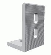
I think I am going to use these:
IMG_0354.jpg

They are aluminum, 3 x 2 x 2”. I am going to use them in pairs, invert one, bolt them together, and create an adjustable Z bracket. It would be much cheaper to make with the right aluminum stock, but I don’t really have the tools to do a good job with it. The foot is also slotted, so it should give me a little bit of adjustment where they are bolted to the panel frame. I was also thinking about mounting the Z brackets on at least one side so that the the bolt could be loosened, and then the opposite side is detached the panel could hinge up to access the roof underneath.

I am thinking that with 4sq-in of surface area, using either 3M 4200 or Sika 391 should be good. I’ve also considered using the 3M VHB tape and then sealing the edge with 4200.
 
I don't understand why you are using such a large fuse when the panels only produce less than 6A each. And for sizing, you should use the short circuit current (Isc), and the open circuit voltage (Voc). For land installation you are then supposed to add 15% margin for both. Land systems also need to be fused at the panel combiner box, and for roof installations the wires need to be in metal conduit inside the house until they reach the fuses. It is also standard practice to put breakers on both the inputs and outputs of the charge controller for easy service.

There have been lots of suggests on way to eliminate some of these measures, and you will need to make your own assessment of what you are comfortable with.

It's unclear if you are commenting on my post, or dhays, but if mine, the Isc is 6.07A and the Voc is 69.7V for each individual panel.

I wasn't going to use a combiner box because I was going to try to use 2 into 1 MC4 connectors at the panel pigtails. These:

https://www.solaris-shop.com/staubli-pv-azb4-mc4-2-female-1-male-connectors/

They would be topsides, under the panels and somewhat accessible.

Am I wrong regarding the wire size from the panel connections to the controller?
I was trying to reduce voltage drop as much as logical, but if I am completely wrong about it, I'll be very happy to use AWG10 or 12. The wire size of the panel leads is AWG12. I was concerned about the combined panel output. As you can see, I am new to this.

As far as a circuit breaker switch between the panels and the controller, if it is more correct to install one that is instantly accessible I can do this and size it to match the appropriate wire size. It wouldn't be located very near the panels, however. It would closer to the controller.

Other than the purchased panels and controller, I'm early enough in the process and can make it any way that is correct. I guess i'm looking for some advice.
 
Muttskie-- #10 wire should work well for you. It is easy to calculate the voltage lost in the wire but with only 11 amperes maximum ....on a brilliant sunny day.... you may loss a volt or two without doing the math and of course knowing the wire length needed for your installation. Two volts lost is less than 3%, peanuts. But again, it is your boat so do make yourself happy. Nobody enjoys doing things over. :thumb:

The wire size from the controller to the batteries is another matter. There you want to keep voltage losses to a minimum within reason.

Got it. Thanks Foggy
 
I wondered about any issues of using stainless hardware with the aluminum mounts and panels, but when I was looking at the mounting instructions for the panels and mounts, they all specified stainless bolts and screws, so I don’t think it should be a problem. Maybe I am just fooling myself?

I have also wondered about using Nylock nuts given the constant vibration.

I think I am going to use these:
View attachment 74226

They are aluminum, 3 x 2 x 2”. I am going to use them in pairs, invert one, bolt them together, and create an adjustable Z bracket. It would be much cheaper to make with the right aluminum stock, but I don’t really have the tools to do a good job with it. The foot is also slotted, so it should give me a little bit of adjustment where they are bolted to the panel frame. I was also thinking about mounting the Z brackets on at least one side so that the the bolt could be loosened, and then the opposite side is detached the panel could hinge up to access the roof underneath.

I am thinking that with 4sq-in of surface area, using either 3M 4200 or Sika 391 should be good. I’ve also considered using the 3M VHB tape and then sealing the edge with 4200.

Dave,
Those brackets look good. How many mounts do you intend to use per panel? I am not going to try to have both of my panels on the same plane, so I don't need the extra height. There will be a very slight angle downward to the outboard edges, so the stick on panels (6 per panel) should be ok. And there will be some air space beneath them.

You should not have dissimilar metal problems with the stainless fasteners and the aluminum brackets if you use some Teff Gel during assembly. It is designed for this very purpose. And self locking nuts is the best choice. You might consider including some nylon, or similar, washers between the stainless washers and the aluminum brackets for additional isolation, as well. Not flimsy plastic. Something that can handle the torque of the tightened fasteners.
 
Dave,

Those brackets look good. How many mounts do you intend to use per panel? I am not going to try to have both of my panels on the same plane, so I don't need the extra height. There will be a very slight angle downward to the outboard edges, so the stick on panels (6 per panel) should be ok. And there will be some air space beneath them.


You should not have dissimilar metal problems with the stainless fasteners and the aluminum brackets if you use some Teff Gel during assembly. It is designed for this very purpose. And self locking nuts is the best choice. You might consider including some nylon, or similar, washers between the stainless washers and the aluminum brackets for additional isolation, as well. Not flimsy plastic. Something that can handle the torque of the tightened fasteners.


We will see how the brackets work out. If I didn’t need the height, I would definitely use those Sticky Feet. The LG mounting instructions say that 4 mounting points are fine. They have 2 sets of pre-drilled holes on the bottom of the panel frame for mounting. One set is about 7” from the ends of the panel and another is almost 12” from the end. I will use the mounting holes 12” from the ends.

I want to set the height so I get a little slope in the panel to help the rain rinse it off. not sure how much is “enough”.

The issues of dissimilar metals is yet another in a plethora of all things nautical that I have complete ignorance. I will definitely get and use some Tef Gel on the stainless/aluminum connections. I looked it up and it sounds like a good idea. I will check out the possibility of nylon washers.
 
I took a different approach to mounting my panels as I described in earlier posts. I found that the advantage of adhesives eliminated drilling unnecessary holes (potential leaks) and eliminating hardtop stress points that brackets might generate. Also bracket stress points can be exacerbated with snow loads if the boat is stored in cold climates uncovered.

And my panels are raised enough to allow cooling and are positioned so the hardtop's curvature is countered by shimming with a piece of plastic board purchased at Lowes placed under one edge of the panel. My mounting solution is just another approach to mounting a panel that is worth sharing.
 
Back
Top Bottom